
A Parameter Design Method for Focusing Light Field Camera System

A technology of light field camera and parameter design, which is applied to the parts of TV system, parts of color TV, TV, etc. It can solve the problems of limiting spatial resolution and achieve reasonable and effective effects of the system

Active Publication Date: 2021-10-29
ZHEJIANG UNIV
View PDF9 Cites 0 Cited by
  • Summary
  • Abstract
  • Description
  • Claims
  • Application Information

AI Technical Summary

Problems solved by technology

However, light field cameras with this structure maximize the angular resolution of the light field image, thus limiting the spatial resolution

Method used


Image

  • A Parameter Design Method for Focusing Light Field Camera System
  • A Parameter Design Method for Focusing Light Field Camera System
  • A Parameter Design Method for Focusing Light Field Camera System

Examples


Embodiment

[0052] In this embodiment, it is assumed that a focus-type light field camera applied in the long-wave infrared band is selected. Suppose the parameters of this focusing light field camera are as follows: working distance 20-100m, detector resolution 640*480, pixel size 15um, imaging main wavelength 10um, main lens focal length 100mm, main lens F-number 1.2.

[0053] Then the parameter design method of the focused light field camera system that meets the above requirements includes the following steps:

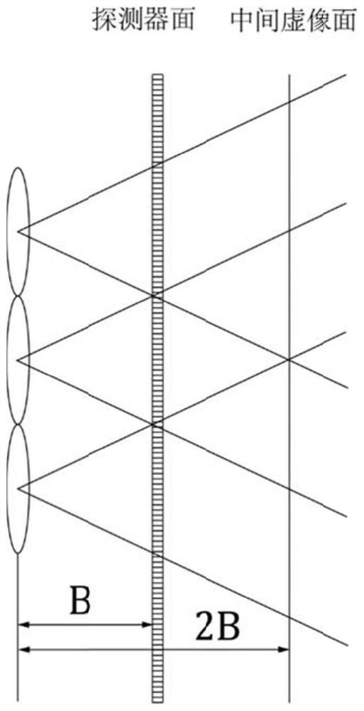
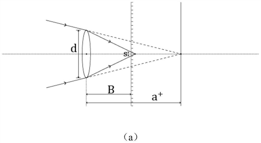
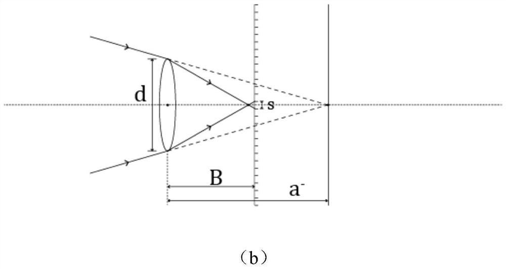
[0054] Step S100, determine the allocation relationship between the spatial resolution and the angular resolution of the focused light field camera, and use M to represent the ratio of the object-to-image distance in the microlens imaging space, that is,

[0055]

[0056] see figure 1 , because the ratio of the object-to-image distance in the microlens imaging space controls the distribution of spatial and angular resolution, and its value also limits whether the depth val...


PUM


Abstract

The invention relates to a parameter design method of a focused light field camera system, which belongs to the field of computational imaging. Utilizing the flexible structure of the focused light field camera, the influence of the internal geometric parameters of the light field camera on the imaging effect of the system is obtained from the analysis of the resolution of the light field image, so that the appropriate system structure parameters can be selected according to the actual needs, and the maximum The performance of existing detectors and optical structures is fully utilized to complete the design of the system. Through the principle of geometric optics, analyze the imaging relationship between the main lens and the microlens array, determine the distribution of spatial and angular resolution through the ratio of the microlens imaging object to image distance, and then combine the analysis of the depth resolution and imaging depth range to obtain the focus comprehensively. The system design parameters of the type light field camera. The design method proposed by the present invention can provide corresponding design schemes for the focused light field camera in different application scenarios, and provide a theoretical basis for the calculation of the accuracy of the light field depth estimation.

Description

technical field [0001] The invention relates to the field of computational imaging, in particular to a parameter design method of a focused light field camera system. Background technique [0002] With the rapid development of computational imaging, obtaining 3D information through light field imaging has attracted some attention in recent years. The light field, that is, the field distribution of light radiating in space, is a high-dimensional data. Therefore, after the light field data is collected, the required information can be extracted from it, such as three-dimensional information in space. [0003] As one of the representatives of the light field imaging system, the light field camera based on the microlens array was proposed by E. Adelson et al. in 1992. This camera is also called a plenoptic camera (Plenoptic Camera). In 2005, R.Ng and others improved the process so that the microlens and the detector can be directly coupled, eliminating the need for a relay syst...

Claims


Application Information

Patent Timeline
Patent Type & Authority Patents(China)
IPC IPC(8): H04N5/232
CPCH04N23/675H04N23/67H04N23/80
Inventor 刘旭朱斐越
Owner ZHEJIANG UNIV
Learn More