
Rotating equipment fault monitoring method and system based on big data and readable storage medium

A rotating equipment and fault monitoring technology, which is applied in the direction of instruments, character and pattern recognition, computer components, etc., can solve problems such as misdiagnosis of uncertain fault diagnosis information, large deviation of fault diagnosis, and wrong maintenance, etc., so as to improve the accuracy of fault monitoring , Improving diagnostic accuracy and reducing acquisition errors

Inactive Publication Date: 2021-01-15
苏州容思恒辉智能科技有限公司
View PDF0 Cites 1 Cited by
  • Summary
  • Abstract
  • Description
  • Claims
  • Application Information

AI Technical Summary

Problems solved by technology

[0002] Vibration fault diagnosis is an indirect diagnosis method based on vibration signal analysis. The vibration signal reaches the vibration sensor through a complex path of the mechanical system. The fault signal is inevitably disturbed during the transmission process. Uncertain fault diagnosis information after complex transmission is easily caused. Misdiagnosis, the occurrence of misdiagnosis will lead to excessive maintenance or wrong maintenance, and even lead to major safety accidents
[0003] The existing fault diagnosis is only to detect the simple vibration signal of the rotating equipment, and based on this to monitor the fault of the rotating equipment, the monitoring fault diagnosis deviation is relatively large. The vibration signal is vector decomposed, and the vibration vectors in different directions are analyzed and reconstructed separately, and the results obtained have large deviations.

Method used

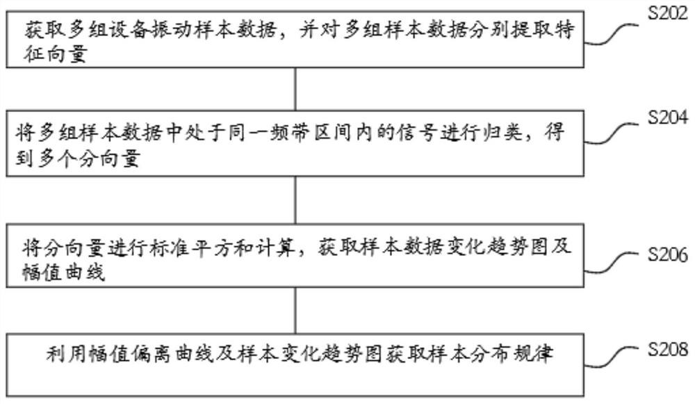
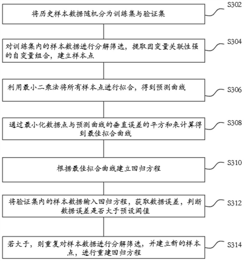

Image

  • Rotating equipment fault monitoring method and system based on big data and readable storage medium
  • Rotating equipment fault monitoring method and system based on big data and readable storage medium
  • Rotating equipment fault monitoring method and system based on big data and readable storage medium

Examples


Embodiment Construction

[0074] In order to understand the above-mentioned purpose, features and advantages of the present invention more clearly, the present invention will be further described in detail below in conjunction with the accompanying drawings and specific embodiments. It should be noted that, in the case of no conflict, the embodiments of the present application and the features in the embodiments can be combined with each other.

[0075] In the following description, many specific details are set forth in order to fully understand the present invention. However, the present invention can also be implemented in other ways different from those described here. Therefore, the protection scope of the present invention is not limited by the specific details disclosed below. EXAMPLE LIMITATIONS.

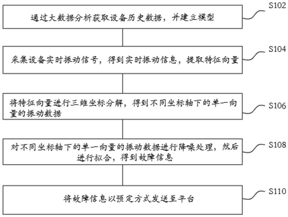
[0076] figure 1 A flow chart of a big data-based fault monitoring method for rotating equipment of the present invention is shown.

[0077] Such as figure 1 As shown, the first aspect of the prese...


PUM


Abstract

The invention relates to a rotating equipment fault monitoring method and system based on big data and a readable storage medium, and the method comprises the steps: setting a sampling interval time,generating multiple groups of sample data of different time nodes, and carrying out the standardization of the multiple groups of sample data, and obtaining standard sample data; obtaining historicalsample data through big data analysis, and establishing a regression model; inputting the standard data into a regression model to obtain a plurality of fault prediction samples; performing similaritycalculation on the plurality of fault prediction samples; classifying the sample data of which the similarity is smaller than a preset threshold value to obtain result information; and performing equipment fault diagnosis through the result information.

Description

technical field [0001] The invention relates to a method for monitoring faults of rotating equipment, in particular to a method, system and readable storage medium for monitoring faults of rotating equipment based on big data. Background technique [0002] Vibration fault diagnosis is an indirect diagnosis method based on vibration signal analysis. The vibration signal reaches the vibration sensor through a complex path of the mechanical system. The fault signal is inevitably disturbed during the transmission process. Uncertain fault diagnosis information after complex transmission is easily caused. Misdiagnosis, the occurrence of misdiagnosis will lead to over-maintenance or wrong maintenance, and even lead to major safety accidents. [0003] The existing fault diagnosis is only to detect the simple vibration signal of the rotating equipment, and based on this to monitor the fault of the rotating equipment, the monitoring fault diagnosis deviation is relatively large. The ...

Claims


Application Information

Patent Timeline
Patent Type & Authority Applications(China)
IPC IPC(8): G06K9/62G06K9/00
CPCG06F2218/08G06F2218/12G06F18/214
Inventor 刘立斌付俊宇
Owner 苏州容思恒辉智能科技有限公司
Learn More