Gearbox fault prediction, monitoring and diagnosis method and corresponding device
A technology of fault prediction and fault diagnosis model, applied in the field of gearboxes, which can solve problems such as inability to predict train gearboxes in a timely and accurate manner
- Summary
- Abstract
- Description
- Claims
- Application Information
AI Technical Summary
Problems solved by technology
Method used
Image
Examples
Embodiment 1
[0030] According to an embodiment of the present invention, a gearbox failure prediction method is provided. It should be noted that the steps shown in the flow chart of the accompanying drawings can be executed in a computer system such as a set of computer-executable instructions, and, although A logical order is shown in the flowcharts, but in some cases the steps shown or described may be performed in an order different from that shown or described herein.
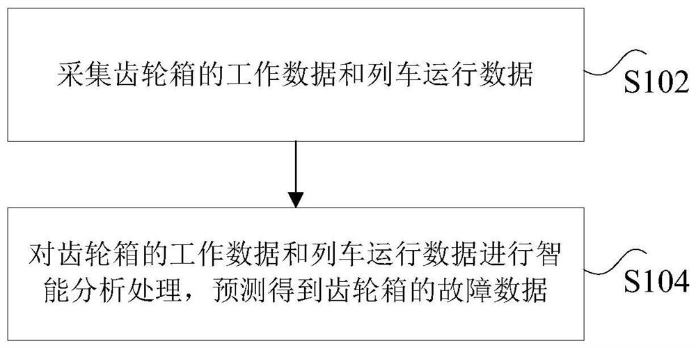
[0031] figure 1 is a schematic diagram of a gearbox failure prediction method provided according to Embodiment 1 of the present invention, as figure 1 As shown, the method includes the following steps:
[0032] Step S102, collecting working data and train running data of the gearbox;
[0033] Step S104, intelligently analyzing and processing the working data of the gearbox and the train operation data, and predicting and obtaining the fault data of the gearbox.
[0034] Through the above steps, the purpose of predic...
Embodiment 2
[0063] Based on the gearbox fault prediction method in Embodiment 1 of the present invention, Embodiment 2 provides a gearbox fault prediction device that can be used to implement the above gearbox fault prediction method. Figure 6 is a structural block diagram of a gear box fault prediction device provided according to Embodiment 2 of the present invention, such as Figure 6 As shown, the gear box fault prediction device 60 includes: a first acquisition unit 602 and a first processing unit 604, and the device will be described below.
[0064] The first collection unit 602 is used to collect working data of the gearbox and train operation data;
[0065] The first processing unit 604 is connected to the above-mentioned first acquisition unit 602, and is used for intelligently analyzing and processing the working data of the gearbox and the train operation data, and predicting and obtaining the failure data of the gearbox.
[0066] It should be noted here that the above-mentio...
Embodiment 3
[0074] According to an embodiment of the present invention, a device for realizing the above-mentioned gear box fault diagnosis method is provided. Figure 8 is a structural block diagram of a gearbox fault diagnosis device provided according to Embodiment 3 of the present invention, as Figure 8 As shown, the gear box fault diagnosis device 80 includes: a second acquisition unit 802, a first preprocessing unit 804, a first screening unit 806, a first feature engineering unit 808 and a second processing unit 810, and the following is performed on the device illustrate.
[0075] The second collection unit 802 is used to collect working data of the gearbox and train operation data;
[0076] The first pre-processing unit 804 is connected to the above-mentioned second acquisition unit 802, and is used to pre-process the working data of the gearbox and the train operation data to obtain pre-processed data;
[0077] The first screening unit 806 is connected to the above-mentioned ...
PUM
 Abstract
Description
Claims
Application Information
 - R&D
- Intellectual Property
- Life Sciences
- Materials
- Tech Scout
- Unparalleled Data Quality
- Higher Quality Content
- 60% Fewer Hallucinations
Browse by: Latest US Patents, China's latest patents, Technical Efficacy Thesaurus, Application Domain, Technology Topic, Popular Technical Reports.
© 2025 PatSnap. All rights reserved.Legal|Privacy policy|Modern Slavery Act Transparency Statement|Sitemap|About US| Contact US: help@patsnap.com


