Automatic marking device for end part of pipe rod body and marking equipment for end part of pipe rod body

A technology of automatic identification and pipe sticks, applied in printing, stamping and other directions, can solve problems such as low efficiency, and achieve the effect of convenient installation and disassembly

Active Publication Date: 2021-01-15
XI AN JIAOTONG UNIV
View PDF19 Cites 0 Cited by
  • Summary
  • Abstract
  • Description
  • Claims
  • Application Information

AI Technical Summary

Problems solved by technology

[0002] For cylindrical pipe rods, different production batches usually require different labels to distinguish them in the industrial production process. At present, it is mainly based on manual hand-held stamps to mark the ends, and the efficiency is relatively low.

Method used


Image

  • Automatic marking device for end part of pipe rod body and marking equipment for end part of pipe rod body
  • Automatic marking device for end part of pipe rod body and marking equipment for end part of pipe rod body
  • Automatic marking device for end part of pipe rod body and marking equipment for end part of pipe rod body

Examples


Embodiment Construction

[0037] The present invention will be further described below in conjunction with the accompanying drawings and embodiments.

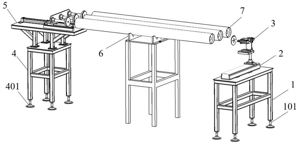
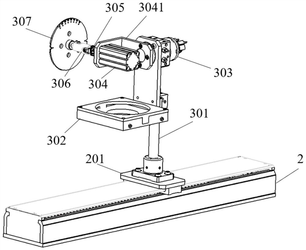
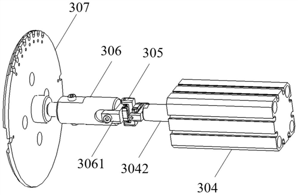
[0038] refer to figure 1 and figure 2 , the present invention is used for the automatic marking device of pipe rod body end, comprises linear slide table 2, printing pad box support seat 301, printing pad box 302, rotary cylinder 303, linear cylinder 304, buffer device 306 and stamp head 307, described printing pad The box support base 301 is installed on the slide table connecting plate 201 of the linear slide table 2, the ink pad box 302 is installed on the ink pad box support base 302, and the rotary cylinder 303 is installed on the ink pad box support base 302 and is located above the ink pad box 302. Plate 3041 is installed on the output shaft of rotary cylinder 303, and linear cylinder 304 is installed on the adapter plate 3041, and the linear cylinder guide rod 3042 of linear cylinder 304 is connected with stamp head 307 by buffer device 306; ...


PUM


Abstract

The invention discloses an automatic marking device for the end part of a pipe rod body and marking equipment for the end part of the pipe rod body. In the automatic marking device, an inkpad box supporting base is installed on a sliding platform connecting plate of a linear sliding platform, an inkpad box is installed on the inkpad box supporting base, and a rotating air cylinder is installed onthe inkpad box supporting base and located above the inkpad box. An adapter plate is installed on an output shaft of the rotating air cylinder, a linear air cylinder is installed on the adapter plate,and a linear air cylinder guide rod of the linear air cylinder is connected with a seal head through a buffering device. The linear air cylinder is located above the inkpad box and can drive the sealhead to stretch into the inkpad box or to be pulled out of the inkpad box. By means of the machine, the purposes that the seal head is automatically dipped in inkpad, and marking is conducted on theend face of the pipe rod body can be achieved, so that the labor is liberated, and the marking efficiency is also improved.

Description

technical field [0001] The invention belongs to the technical field of automatic stamping equipment, and in particular relates to an automatic marking device and marking equipment for the ends of pipe rods. Background technique [0002] For cylindrical tube rods, different production batches usually require different labels to distinguish them in the industrial production process. At present, it is mainly based on manual hand-held stamps to mark the ends, and the efficiency is relatively low. Contents of the invention [0003] In order to solve the problems existing in the prior art, the purpose of the present invention is to provide an automatic marking device and marking equipment for the end of the pipe and rod body. The present invention can improve the marking of the end of the cylindrical pipe rod time efficiency. [0004] To achieve the above object, the present invention adopts the following technical solutions: [0005] An automatic marking device for the end of...

Claims


Application Information

Patent Timeline
IPC IPC(8): B41K3/00B41K3/62B41K3/54
CPCB41K3/00B41K3/62B41K3/54
Inventor 徐海波刘旭阳薛海洋沈翁炀陈家豪
Owner XI AN JIAOTONG UNIV
Why Eureka
Try Eureka