
Laser cutting device

A laser cutting and cutting machine technology, applied in laser welding equipment, welding equipment, metal processing equipment, etc., can solve the problems of cutting head damage, no protective device, cutting head temperature rise, etc., to keep clean, easy to clean, and convenient The effect of observation

Inactive Publication Date: 2021-01-15
许同
View PDF0 Cites 4 Cited by
  • Summary
  • Abstract
  • Description
  • Claims
  • Application Information

AI Technical Summary

Problems solved by technology

[0004] The object of the present invention is to provide a laser cutting device to solve the problem that the temperature of the laser is high in the above-mentioned background technology, and there is no corresponding protective device in the cutting process, and the temperature of the cutting head will rise sharply after the cutting time is too long , resulting in damage to the cutting head, and at the same time, the cutting waste generated by the existing large laser cutting machine after cutting is not easy to clean up

Method used


Image

  • Laser cutting device
  • Laser cutting device
  • Laser cutting device

Examples


Embodiment Construction

[0029]The technical solutions in the embodiments of the present invention will be clearly and completely described below in conjunction with the accompanying drawings in the embodiments of the present invention. Obviously, the described embodiments are only a part of the embodiments of the present invention, rather than all the embodiments. Based on the embodiments of the present invention, all other embodiments obtained by those of ordinary skill in the art without creative work shall fall within the protection scope of the present invention.

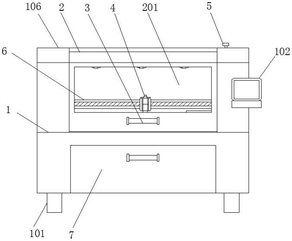
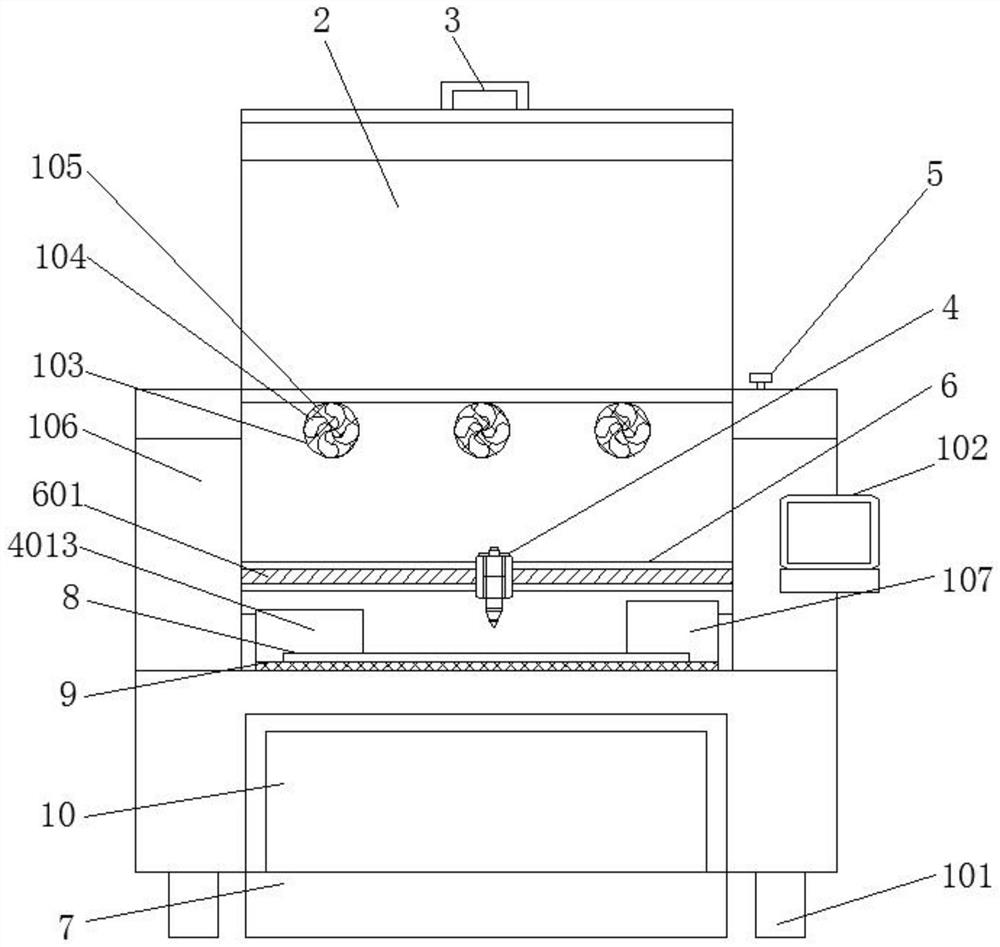
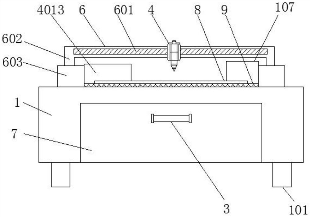
[0030]SeeFigure 1-7, The present invention provides a technical solution: a laser cutting device, such asfigure 1 ,figure 2 withimage 3 As shown, a protective box 106 is installed on the top of the cutting machine body 1, four feet 101 are installed at the bottom of the cutting machine body 1, an emergency stop button 5 is installed on the top right side of the cutting machine body 1, and a heat dissipation hole is provided on the back of the p...


PUM


Abstract

The invention discloses a laser cutting device. The laser cutting device comprises a cutting machine main body, a cutting head and a cutting frame, wherein a protection box body is mounted above the cutting machine main body, a protection box cover is mounted in the protection box body, a waste box door is formed in the lower part of the cutting machine main body, and a control panel is mounted outside the cutting machine body; a cutting head and a cutting frame are mounted in the cutting machine main body, a light inlet cylinder is arranged above the cutting head, a cooling plate is mounted on the back of the cutting head, a laser emitting head is arranged below the cutting head, a cooling protection sleeve is mounted outside the laser emitting head, and the cutting frame is mounted abovea sliding frame. A first electric sliding rail is arranged in the cutting frame, and the cutting head is slidably mounted on the cutting frame. The laser cutting device is provided with the protective box body, the protective box cover and an observation window, a cut part is covered, the protective box cover is mounted in the protective box body, and meanwhile, the observation window is formed in the protective box cover, and therefore, it is convenient for an operator to observe a cutting process.

Description

Technical field[0001]The invention relates to the technical field of laser cutting devices, in particular to a laser cutting device.Background technique[0002]Laser cutting is to focus the laser light emitted from the laser into a high-power density laser beam through the optical path system. The laser beam irradiates the surface of the workpiece to reach the melting point or boiling point. At the same time, the high-pressure gas coaxial with the beam will melt or gas. The metal is blown away, as the relative position of the beam and the workpiece moves, the material will finally form a slit to achieve the purpose of cutting. With the continuous development of laser technology, more and more mature laser technology is applied in various fields, for example, Laser marking, laser printing, laser cutting, laser welding, laser ranging, etc. The laser has the characteristics of strong directionality, high brightness and concentrated energy.[0003]However, in the existing laser cutting mach...

Claims


Application Information

Patent Timeline
Patent Type & Authority Applications(China)
IPC IPC(8): B23K26/38B23K26/14B23K26/70
CPCB23K26/14B23K26/38B23K26/703
Inventor 许同
Owner 许同
Learn More