
An integral dust removal device and dust removal method for a computer room with ventilation and deodorization functions

A dust removal device, an integral technology, applied in the field of integral dust removal devices for computer rooms with ventilation and deodorization functions, can solve the problems that operators cannot use it conveniently, the cleaning degree of the computer room is not enough, and the operation time is long, so as to speed up the dust removal process, Speed ​​up processing and avoid messy effects

Active Publication Date: 2021-08-17
衡阳佳鑫信息技术有限公司
View PDF6 Cites 0 Cited by
  • Summary
  • Abstract
  • Description
  • Claims
  • Application Information

AI Technical Summary

Problems solved by technology

[0005] Aiming at the deficiencies of the prior art, the present invention provides an integral machine room dust removal device and dust removal method with ventilation and deodorization functions, mainly to solve the problem that the cleaning degree of the machine room is not enough, resulting in too long operation time, so that the operator cannot conveniently problem of use

Method used


Image

  • An integral dust removal device and dust removal method for a computer room with ventilation and deodorization functions
  • An integral dust removal device and dust removal method for a computer room with ventilation and deodorization functions
  • An integral dust removal device and dust removal method for a computer room with ventilation and deodorization functions

Examples


Embodiment 1

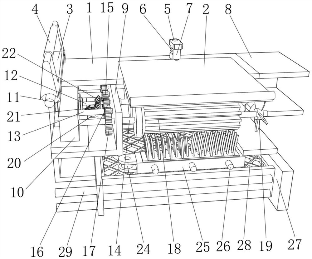
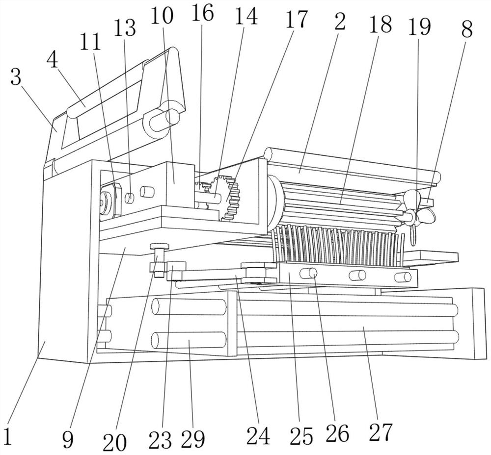
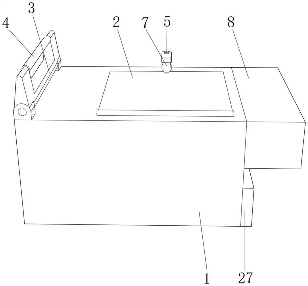
[0036] refer to Figure 1-5 , an integral machine room dust removal device with ventilation and deodorization functions and a dust removal method, comprising the following steps:

[0037]S1: To move the position, the operator lifts the anti-skid cylinder 4 on the handle bar, and directs the air cylinder 8 on the housing 1 to the dust-removing position in the machine room;

[0038] S2: Starting device, start the motor 11, the motor 11 drives the connecting shaft 12 to rotate, the driving gear 15 on the connecting shaft 12 drives the two driven gears 16 to rotate, the driven gear 16 drives the rotating gear 17 and the linkage shaft 14 to rotate, the connecting shaft 12 and two linkage shafts 14 drive the impeller 19 and the rotating blades to rotate, generate suction, and perform dust suction operations on the machine room. The dust sucked by the connecting shaft 12 and the turret 18 on the linkage shaft 14 will be attached, and then the dust will be sucked by the connecting sha...

Embodiment 2

[0046] refer to Figure 1-6 , the bottom of the housing 1 is rotatably connected with a frame 31, the upper surface of the frame 31 is movably connected with a telescopic rod 30, one end of the telescopic rod 30 is movably connected with the bottom of the housing 1, and the housing 1 and the frame 31 are connected through the telescopic rod 30 The setting of the movable connection can mechanically tilt the housing 1 and the air duct 8, so as to expand the working range of dust removal in the machine room. The bottom of the frame 31 is fixed with a plurality of mounting plates 32 by bolts, and the bottoms of the multiple mounting plates 32 are equipped with bearings. , the inner walls of multiple bearings are plugged with connecting plates 33, and the direction of the dust removal device can be reversed by setting the bearings at the bottom of the mounting plate 32, which is convenient for the operator to operate. The bottoms of multiple connecting plates 33 are fixed by bolts. ...


PUM


Abstract

The invention relates to the technical field of machine room cleaning, and discloses an integral machine room dust removal device with ventilation and deodorization functions and a dust removal method. S2: Start the device, start the motor, the motor drives the connecting shaft to rotate, the driving gear on the connecting shaft drives the two driven gears to rotate, and the driven gear drives the rotating gear Rotating with the linkage shaft, the connecting shaft and the two linkage shafts drive the impeller and the rotor blades to rotate, generate suction, and perform dust collection operations on the machine room. The present invention can avoid the excessive operation of its power, and ensure that the dust removal device can carry out dust removal operations in the machine room multiple times and in many ways, and the dust in the device can be used for dust reduction operations. The dust removal operation of the device is carried out.

Description

technical field [0001] The invention relates to the technical field of machine room cleaning, in particular to an integral machine room dust removal device with ventilation and deodorization functions and a dust removal method. Background technique [0002] With the rapid development of the Internet and the popularization and use of computers, many units and schools have computer rooms, and these computer rooms are frequently used. Due to the large flow of people in the computer room, people will frequently move between classes or during training, and all computers run simultaneously in a limited time and space. The static electricity released by electronic equipment is easy to absorb dust in the air. These dusts have It may cause the computer system to crash, and even cause the computer to discharge abnormally. After a long time, it will easily cause the hardware failure of the computer. At the same time, the accumulation of more static electricity will also cause electric...

Claims


Application Information

Patent Timeline
Patent Type & Authority Patents(China)
IPC IPC(8): B08B15/00B01D50/00
CPCB08B15/00B01D50/60
Inventor 周理方匡新平周刚谭绪云
Owner 衡阳佳鑫信息技术有限公司
Learn More