Improved filter press

A filter press and rack technology, applied in the field of solid-liquid separation, can solve the problems of low filter press efficiency, increased filter press cost, slow rotation of fan blades, etc., to reduce workload, enhance use safety, and enhance The effect of filter press

Active Publication Date: 2021-01-15
福建省创绿机械股份有限公司
View PDF13 Cites 3 Cited by
  • Summary
  • Abstract
  • Description
  • Claims
  • Application Information

AI Technical Summary

Problems solved by technology

In the process of pressing the filter, there is a problem that the filter residue blocks the filter cloth and affects the filter press. For this reason, Patent Document 1 proposes a filter press, which is provided with a spring and a rotatable filter between the filter cloth and the filter plate. The structure of the push rod, the joint action of the spring and the push rod makes the relative movement between the filter cloth and the filter plate possible, and to a certain extent avoids the situation that the filter holes on the filter cloth are blocked by fixed particles. However, due to the Spring structure, so the push rod structure cannot completely cover the entire filter cloth, and because the longitudinal section area of ​​the push rod gradually decreases toward the side of the filter cloth, the end of the push rod away from the filter plate is rounded Therefore, the push rod is not a flexible structure, and the filter cloth may be damaged by cutting or the like during the rotation. After passing through the feed inlet, the fan blades are driven to rotate. At the beginning of flushing, because the filter chamber is not filled with liquid, the fan blades rotate faster, but after the liquid is filled, the liquid passing through the feed inlet will become less or flow. Slowly, at this time, the fan blade may rotate slowly or cannot rotate, and at this time, the push rod may not rotate. Therefore, there is a situation that the filter cloth and the filter plate cannot be relatively separated and bonded
Another example is patent document 2, which discloses a high-efficiency box-type filter press with dynamic water circulation. This filter press takes into account the sludge deposition in the sewage during the press filtration process, resulting in uneven distribution of sludge concentration inside the sewage, increasing the In the case of the pressure filter load of the filter press, an additional circulation pump is installed, which is used to suck the sewage at the bottom into the circulation pump, and then input the sucked sewage from the top of the container, so that the whole sewage can circulate , so that no deposition will occur, but this structure further increases the cost of the filter press due to the additional circulation pump, and because the box is a sealed structure, only the tail is provided with a mud discharge port 10, therefore, Its filter press efficiency is low, and the press filter effect is not ideal; another example is Patent Document 3, which discloses an intelligent fully hydraulic deep dehydration automatic filter press, which is provided with a small filter between the left and right plate frames of the plate frame. The oil cylinder uses a small oil cylinder to replace the traditional spring to increase the volume of the filter chamber through the small oil cylinder before pressing the filter. Relying on the cooperation between the small oil cylinder and the main oil cylinder to reduce the filter chamber, the reliability of the system is improved, but it is on the filter cloth. When the sludge is processed, an additional blanking mechanism is set up, and the separation of the mud cake from the filter cloth is realized by the vibration motor in the shaking blanking mechanism, which requires more energy.

Method used


Image

  • Improved filter press
  • Improved filter press
  • Improved filter press

Examples


Embodiment Construction

[0038] The present invention will be further described below in conjunction with the examples, but the present invention is not limited in any way, and any transformation or substitution made based on the teaching of the present invention belongs to the protection scope of the present invention.

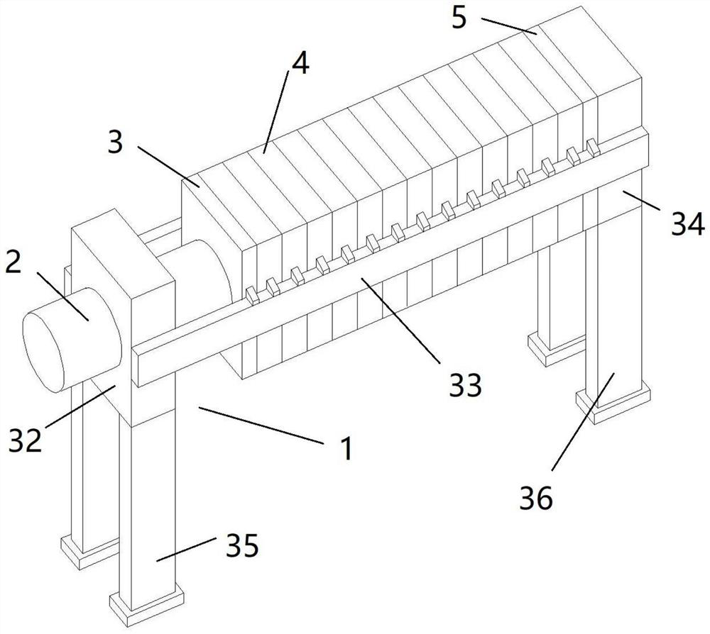
[0039] Such as figure 1 As shown, the improved filter press of the present invention includes: a frame 1, a hydraulic cylinder 2, a pressing plate 3, a filter plate 4 and a thrust plate 5, and the frame 1 includes a left support frame 32, a beam 33 and a right support frame 34 , the two ends of the beam 33 are respectively connected to the left support frame 32 and the right support frame 34, the compression plate 3 and the filter plate 4 are slidably arranged on the beam 33, the hydraulic cylinder 2 is fixedly arranged on the left support frame 32, and the end is connected with the compression plate 3. Fixedly connected, the thrust plate 5 is fixedly arranged on the right support fr...


PUM


Abstract

The invention discloses an improved filter press, which is characterized in that a flexible linkage mechanism is creatively applied to the filter press, and flowing of feed liquid is used as power output at the same time, so that the flexible linkage mechanism can actively fluctuate to drive filter cloth to shake up and down all the time. Meanwhile, due to the fact that the flexible linkage mechanism can transmit locally excessive fluctuating force to the whole flexible linkage mechanism, the filter cloth can be evenly stressed on the whole. Meanwhile, the fluctuating filter cloth can ensure that filter holes are not blocked, water in filter residues can be discharged more sufficiently, and the filter pressing effect is improved.

Description

technical field [0001] The invention relates to the technical field of solid-liquid separation, in particular to an improved filter press. Background technique [0002] Filter press, especially box-type filter press, is a commonly used solid-liquid separation equipment, which has the advantages of high filtration pressure, large single-machine filtration area, low liquid content of filter cake, light weight of filter plate, and low maintenance and operation costs. Therefore, its application is more extensive. The box-type filter press consists of a set of filter chambers arranged alternately with filter plates and filter frames. The filter frames and filter plates are provided with through holes. After assembly, a complete channel can be formed, and the suspension, washing water and filtrate can be introduced. Under the pressure of the feeding pump, the material liquid to be filtered is sent into each filter chamber, and the solid and liquid are separated through the filter...

Claims


Application Information

Patent Timeline
Patent Type & Authority Applications(China)
IPC IPC(8): B01D25/12
CPCB01D25/12
Inventor 王金伟庞碧达
Owner 福建省创绿机械股份有限公司
Why Eureka
Try Eureka