
Rotor core and rotor shaft press-fitting assembly line

A technology of rotor iron core and rotor shaft, which is applied in the manufacture of stator/rotor body, electromechanical device, and motor generator, etc. It can solve the problem of uneven clamping force, inability to apply workpiece clamping of various specifications, and troublesome adjustment, etc. question

Active Publication Date: 2021-01-12
ZHEJIANG LINIX MOTOR
View PDF10 Cites 8 Cited by
  • Summary
  • Abstract
  • Description
  • Claims
  • Application Information

AI Technical Summary

Problems solved by technology

[0005] The purpose of the present invention is to provide a rotor core and rotor shaft press assembly line, which solves the problems in the prior art that it cannot be used for clamping workpieces of various specifications, and at the same time, the clamping force is uneven and the adjustment is troublesome.

Method used


Image

  • Rotor core and rotor shaft press-fitting assembly line
  • Rotor core and rotor shaft press-fitting assembly line
  • Rotor core and rotor shaft press-fitting assembly line

Examples


Embodiment Construction

[0034]In the following, the technical solutions of the present invention will be further described in detail through embodiments and in conjunction with the drawings.

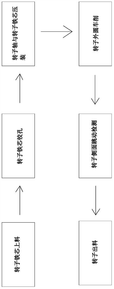
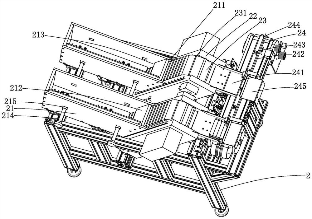
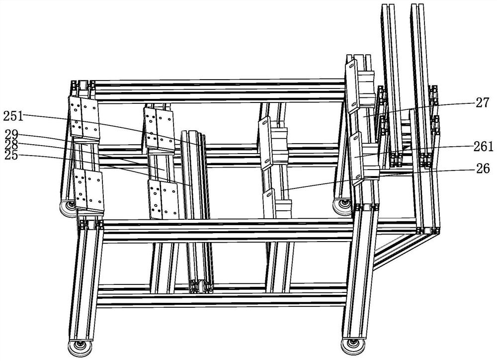
[0035]Such asFigure 1-17 As shown, a rotor core and rotor shaft press assembly line, including rotor core automatic feeding equipment, rotor core automatic reaming equipment, rotor shaft and rotor core press assembly equipment, and rotor external turning Equipment, rotor side runout detection equipment, and rotor automatic discharging equipment. The rotor core automatic reaming equipment includes a first bottom plate 1. A first fixed plate 11 is provided above the first bottom plate 1, and a first fixed plate 11 is provided with a A V-shaped clamping block 111 and a second V-shaped clamping block 112 arranged opposite to the first V-shaped clamping block 111, the first V-shaped clamping block 111 and the second V-shaped clamping block 112 are relatively movable, and the first fixing plate 11 The upper part corresponding...


PUM


Abstract

The invention relates to a rotor iron core and rotor shaft press-fitting assembly line which comprises rotor iron core automatic feeding equipment, rotor iron core automatic reaming equipment, rotor shaft and rotor iron core press-fitting equipment, rotor outer circle turning equipment, rotor side face bounce detection equipment and rotor automatic discharging equipment which are sequentially arranged. The rotor iron core automatic reaming equipment comprises a first bottom plate, a first fixing plate is arranged above the first bottom plate, a first V-shaped clamping block and a second V-shaped clamping block are arranged on the first fixing plate, a first connecting arm and a second connecting arm are arranged below the first fixing plate, one end of the first connecting arm is rotationally connected with the first V-shaped clamping block. The second connecting arm is rotationally connected with the second V-shaped clamping block, and the other end of the first connecting arm and theother end of the second connecting arm are rotationally connected with the same connecting shaft. The clamping device has the advantages of being suitable for workpieces of various specifications, uniform in clamping force, easy and convenient to adjust and the like.

Description

Technical field[0001]The invention relates to a rotor iron core and rotor shaft press assembly line, which belongs to the technical field of automatic rotor production.Background technique[0002]The motor is mainly composed of a rotor and a stator. It is an important device for realizing the transformation from electrical energy to mechanical energy. It is the power source of many automation devices and is widely used in various industries. The motor rotor consists of a shaft and a rotor core. The production process mainly includes compacting the rotor sheet into a whole, and then heating it. After heating, the shaft is pressed into the rotor, and finally it is cooled and pressure-maintained; and the motor rotor It is widely used, and my country has a great demand for motor rotors.[0003]At present, the motor rotor has the following limitations in the machining process: (1) The degree of automation is low and the machining efficiency is low. Although there are equipment for automatic ...

Claims


Application Information

Patent Timeline
IPC IPC(8): H02K15/02H02K15/14
CPCH02K15/02H02K15/14
Inventor 魏中华张敬国陈旺旺张立辉
Owner ZHEJIANG LINIX MOTOR
Learn More