Compact precise driving shaft system with limiting function

A drive shaft, compact technology, applied in the direction of electric components, electromechanical devices, electrical components, etc., can solve the problems of heavy weight, large size, complex structure, etc., and achieve the effect of light weight, large driving force, and high strength and rigidity

Active Publication Date: 2021-01-12
JIUJIANG PRECISION MEASURING TECH RES INST
View PDF13 Cites 0 Cited by
  • Summary
  • Abstract
  • Description
  • Claims
  • Application Information

AI Technical Summary

Problems solved by technology

[0003] The bomb-loaded operating environment imposes strict requirements on the size and weight of the three-auto inertial group dual-axis indexing mechanism. The drive shaft of the existing product uses crossed roller bearings, which is large in size, heavy in weight, and complex in structure. Therefore, it is necessary to modify the existing drive shaft Improve the material and structure of the system to meet the above requirements

Method used


Image

  • Compact precise driving shaft system with limiting function
  • Compact precise driving shaft system with limiting function
  • Compact precise driving shaft system with limiting function

Examples


Embodiment

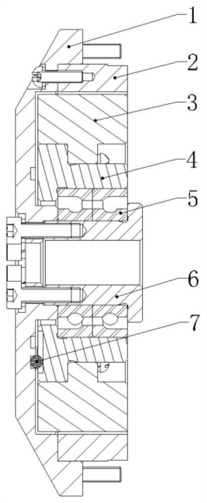
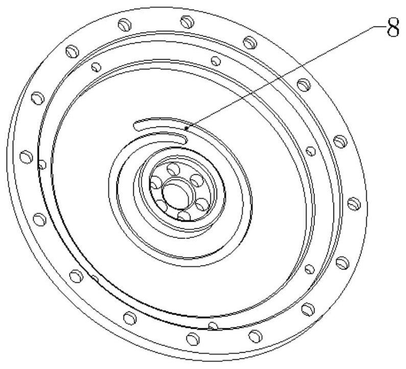
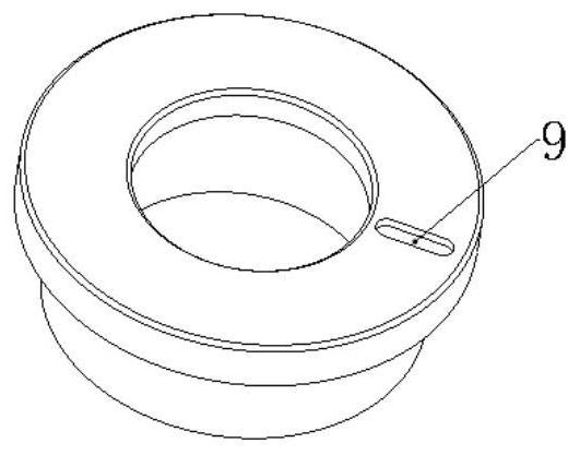
[0017] Such as figure 1 , figure 2 , image 3 As shown, the specific implementation process is as follows:

[0018] A compact precision drive shaft system with a limit, which is applied to the dual-axis indexing mechanism of the bomb-loaded three-auto inertial group, such as figure 1 As shown, the motor stator 2 and the rotating shaft 6 are respectively fixed on the motor base 1 by screws, and the inner rings of the angular contact bearing pairs 5 are fixed on the rotating shaft 6, which jointly constitute the static part of the precision drive shaft system; the angular contact bearing pairs 5 outer rings, The bearing seat 4 and the motor rotor 3 together constitute the rotating part of the precision drive shaft system. The load is fixed on the bearing seat 4 by screws and rotates with the rotating part; the steel ball 7 moves radially on the groove 9 of the bearing seat 4, and at the same time It moves along the helical groove 8 on the motor base 1 and acts as an angle li...


PUM


Abstract

A compact precision driving shafting with a limiting function comprises a motor base, a motor stator, a motor rotor, a bearing base, an angular contact bearing pair, a rotating shaft and a steel ball,wherein the motor stator and the rotating shaft are fixed to the motor base through screws respectively, an inner ring of the angular contact bearing pair is fixed to the rotating shaft to jointly form a static part of the precision driving shafting; the outer ring of the angular contact bearing, the bearing base and the motor rotor jointly form a rotating part of the precision driving shaft system; and the steel ball moves on the groove of the bearing base along the radial direction and moves on the motor seat along the spiral line at the same time to play a role in angle limiting. The precision driving shaft system has the advantages of being high in precision, large in driving force, compact in structure, light in weight, high in strength and rigidity, resistant to impact vibration andthe like, can meet related requirements of missile-borne equipment, can be produced in a modular mode, and is beneficial to shortening the equipment development period and reducing the development cost.

Description

technical field [0001] The invention relates to a precision drive shaft system, in particular to a compact precision drive shaft system with a limit, which is applied to a bomb-loaded three-automatic inertial group dual-axis indexing mechanism. Background technique [0002] As an important part in the development process of the three-automatic inertial group dual-axis indexing mechanism, the drive shaft system is used to drive the rotary motion of the inner frame and the load frame, and to limit the range of motion of the inner frame and load frame. The accuracy of the drive shaft system It directly affects the various motion precision indexes of the whole equipment, and plays a key role in the development process of the three-auto inertial group dual-axis indexing mechanism. [0003] The bomb-loaded use environment imposes strict requirements on the size and weight of the three-auto inertial group dual-axis indexing mechanism. The drive shaft of the existing product uses cr...

Claims


Application Information

Patent Timeline
Patent Type & Authority Applications(China)
IPC IPC(8): H02K7/10H02K7/00
CPCH02K7/10H02K7/003
Inventor 丁德甫黄琛帅高鹏李丰徐程南
Owner JIUJIANG PRECISION MEASURING TECH RES INST
Why Eureka
Try Eureka