


Quick Research
Generate reliable direction feasibility study reports for your R&D in just a few steps.

Technical Q&A
Discover and master advanced knowledge NOW. Basics, ideas, possibilities, all at once.

Find Solutions
As an expert in R&D theories, this can generate solutions to your technical problems instantly.

Evaluate Feasibility
Analyze your overall solution with one click, know your potential R&D risks in advance.

Monitor Landscape
Get weekly tech updates, stay abreast of the latest tech innovations and key insights.
A micro-vibration constant-humidity incubator
A technology of micro-vibration and incubator, which is applied in enzymology/microbiology devices, biomass post-treatment, bioreactors/fermentation tanks for specific purposes, etc., can solve problems affecting the normal cultivation of microorganisms, and achieve good results and high heat evenly distributed effect
- Summary
- Abstract
- Description
- Claims
- Application Information
AI Technical Summary
Problems solved by technology
Method used
Image

Examples
Embodiment 1
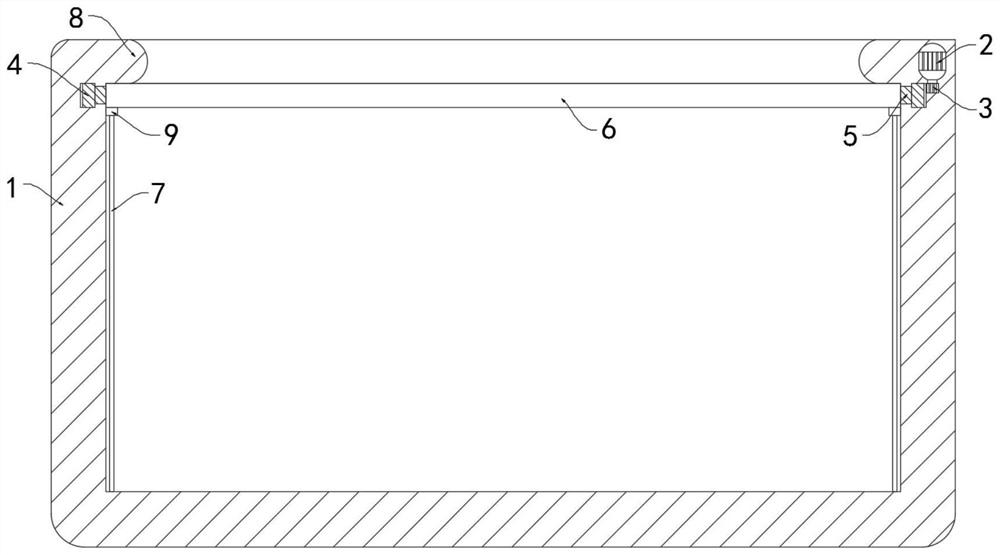
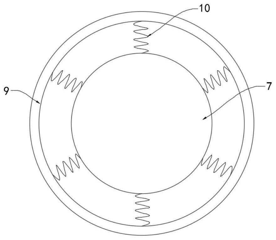
[0025] Such as Figure 1-3 As shown, a micro-vibration constant-humidity constant temperature box includes a box body 1, a power supply and a micro-motor 2. It is worth mentioning that the upper edge of the box body 1 extends inward along its radial direction to form a protective ring 8. The protective ring 8 can play a protective role to the rotating ring 6 below it.
[0026] The power supply is connected with a frequency conversion module, and the frequency conversion module will continuously change the direction of the current. The micro motor 2 is fixedly installed in the side wall of the box body 1. The output end of the micro motor 2 is fixedly connected to the gear 3, and the box body 1 is embedded with an outer gear ring 4. , the outer gear ring 4 is rotatably connected with the side wall of the box body 1, the outer gear ring 4 is meshed with the gear 3, the inner ring side wall of the outer gear ring 4 is fixedly connected with a connecting ring 5, and the connecting...
Embodiment 2
[0033] Such as Figure 4 As shown, the difference between this embodiment and Embodiment 1 is that: the lower side wall of the outer gear ring 4 is fixedly connected with a drum 11, the drum 11 is connected to the side wall of the box body 1 in rotation, and the inner surface of the box body 1 is fixedly embedded. A temperature-conducting layer 12 is provided, and the side wall of the box body 1 between the drum 11 and the temperature-conducting layer 12 is a frictional heating layer 13 .
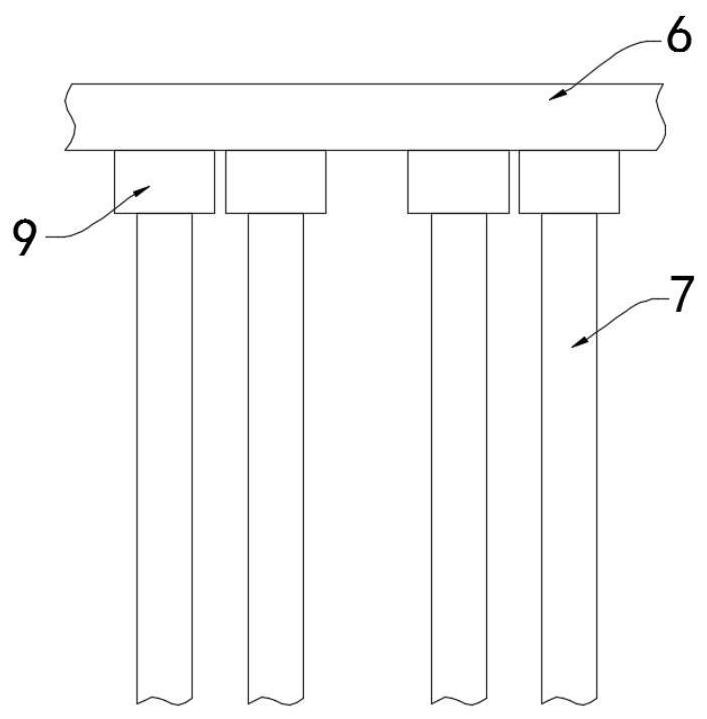
[0034] The capillary strip 7 includes an insulating tube 14, and a plurality of conductive strips 15 are fixedly connected in the insulating tube 14, and a liquid storage tank 16 communicating with the outside is formed between every two conductive strips 15.
[0035] In this embodiment, when the outer gear ring 4 rotates with the gear 3, it will drive the drum 11 to rotate, and the rotating drum 11 will be driven to rub against the friction heating layer 13 to generate heat, and the genera...
PUM
 Abstract
Description
Claims
Application Information
 - R&D Engineer
- R&D Manager
- IP Professional
- Industry Leading Data Capabilities
- Powerful AI technology
- Patent DNA Extraction
Browse by: Latest US Patents, China's latest patents, Technical Efficacy Thesaurus, Application Domain, Technology Topic, Popular Technical Reports.
© 2024 PatSnap. All rights reserved.Legal|Privacy policy|Modern Slavery Act Transparency Statement|Sitemap|About US| Contact US: help@patsnap.com