Eureka AIR delivers breakthrough ideas for toughest innovation challenges, trusted by R&D personnel around the world.

Flue gas on-line monitoring equipment for preventing and treating pollution

A monitoring equipment and flue gas technology, applied in the field of environmental protection equipment, can solve problems such as probe blockage, flue gas blockage, and reduced monitoring accuracy, and achieve the effects of reducing impact, improving efficiency, and avoiding detection accuracy.

Inactive Publication Date: 2021-01-08
杭州中奥工业设计有限公司
View PDF0 Cites 2 Cited by
  • Summary
  • Abstract
  • Description
  • Claims
  • Application Information

AI Technical Summary

Problems solved by technology

The existing online monitoring equipment for pollution prevention and control of flue gas generally adopts a single point and a single intake air extraction mode, and the flue gas can only enter the detection equipment through one point for detection. In the long run, it is easy to cause the flue gas to enter a single fixed point The reason is that when the flue gas is discharged and the air is prone to dirt and particulate impurities, the probe of the flue gas online monitoring equipment will be blocked. In the long run, the monitoring accuracy will be reduced.

Method used


Image

  • Flue gas on-line monitoring equipment for preventing and treating pollution
  • Flue gas on-line monitoring equipment for preventing and treating pollution
  • Flue gas on-line monitoring equipment for preventing and treating pollution

Examples


Embodiment Construction

[0038] The following will clearly and completely describe the technical solutions in the embodiments of the present invention with reference to the accompanying drawings in the embodiments of the present invention. Obviously, the described embodiments are only some, not all, embodiments of the present invention. Based on the embodiments of the present invention, all other embodiments obtained by persons of ordinary skill in the art without making creative efforts belong to the protection scope of the present invention.

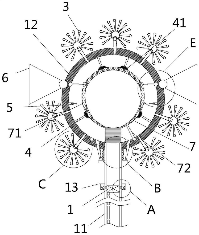
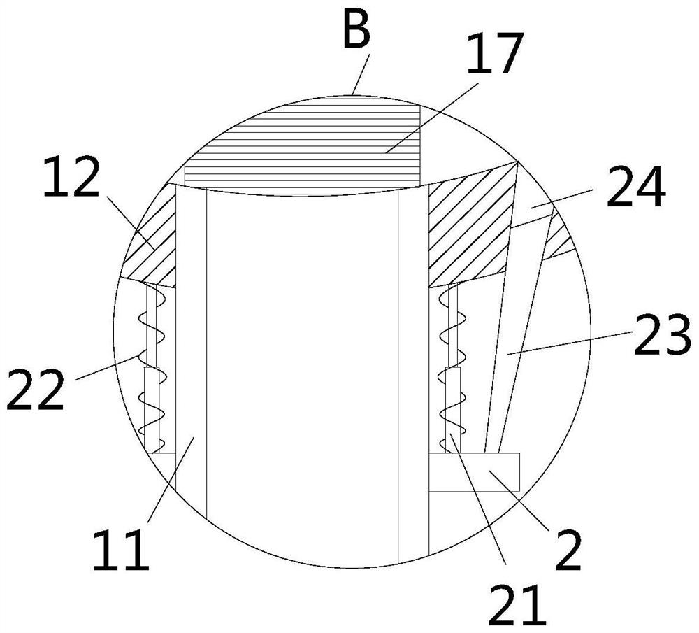
[0039] see Figure 1-10 , the present invention provides a technical solution: smoke online monitoring equipment for pollution prevention and control, a monitoring probe 1 and a bottom cylinder 11, the monitoring probe 1 is arranged in the bottom cylinder 11, and the monitoring probe 1 detects smoke parameters and smoke concentration etc., the monitoring probe 1 is the prior art, and will not be repeated here. The bottom of the monitoring probe 1 is connected ...


PUM


Abstract

The invention relates to the technical field of environmental protection equipment, and discloses flue gas on-line monitoring equipment for preventing and treating pollution. The flue gas on-line monitoring equipment comprises a monitoring probe and a bottom cylinder. The monitoring probe is arranged in the bottom cylinder and fixedly installed on the inner wall in a cavity of the bottom cylinder,a hollow and annular side cylinder is fixedly installed on the outer wall of the bottom cylinder, and an air pump is fixedly installed in the cavity of the side cylinder. A shell is fixedly installedat the top of the bottom cylinder, the top end of the bottom cylinder extends into the bottom of a cavity in the shell, and primary filtering devices distributed in an annular array mode are arrangedon the outer wall of the shell. According to the flue gas online monitoring equipment for preventing and treating pollution, the primary filtering devices are arranged, filtering balls suck air through air suction cylinders of which the outer walls are distributed in an annular array, the air suction cylinders suck air through first filtering nets, and the first filtering nets perform primary filtering on dust and large-size dirt in air, so that the flue gas online detection efficiency is improved, and the problem that in the flue gas online detection process, the detection accuracy is affected by suspended matter and large-size particulate matter in air is solved.

Description

technical field [0001] The invention relates to the technical field of environmental protection equipment, in particular to smoke online monitoring equipment for pollution prevention and control. Background technique [0002] The flue gas detection for pollution prevention is often used for online detection of flue gas discharged from chemical plants or processing plants. The monitoring probe analyzes the discharged flue gas, and then feeds back the detection results to the monitoring center. The existing online monitoring equipment for pollution prevention and control of flue gas generally adopts a single point and a single intake air extraction mode, and the flue gas can only enter the detection equipment through one point for detection. In the long run, it is easy to cause the flue gas to enter a single fixed point The reason is that when the flue gas is discharged and the air is prone to dirt and particulate impurities, the probe of the flue gas online monitoring equipme...

Claims


Application Information

Patent Timeline
IPC IPC(8): G01N1/24G01N1/34B01D46/00B01D46/44B01D46/48
CPCG01N1/2205G01N1/2258G01N1/24G01N1/34B01D46/44B01D46/48B01D46/56B01D46/76B01D46/88
Inventor 平巧丽
Owner 杭州中奥工业设计有限公司
Why Eureka
Eureka Blog
Learn More