


Quick Research
Generate reliable direction feasibility study reports for your R&D in just a few steps.

Technical Q&A
Discover and master advanced knowledge NOW. Basics, ideas, possibilities, all at once.

Find Solutions
As an expert in R&D theories, this can generate solutions to your technical problems instantly.

Evaluate Feasibility
Analyze your overall solution with one click, know your potential R&D risks in advance.

Monitor Landscape
Get weekly tech updates, stay abreast of the latest tech innovations and key insights.
Slow feeding fixture for high-precision hole
A high-precision, wire-clamping technology, applied in the direction of clamping, manufacturing tools, supports, etc., can solve the problems that the clamps cannot achieve the clamping and fixing effect, cannot process parts with high tight holes, and affect the quality and efficiency of parts production. Good clamping and fixing effect, good high-tight hole machining operation, and the effect of improving production quality and efficiency
- Summary
- Abstract
- Description
- Claims
- Application Information
AI Technical Summary
Problems solved by technology
Method used
Image

Examples
Embodiment 1
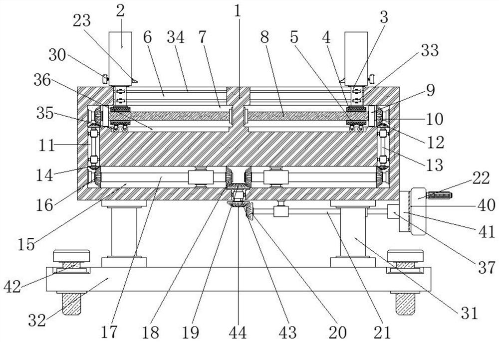
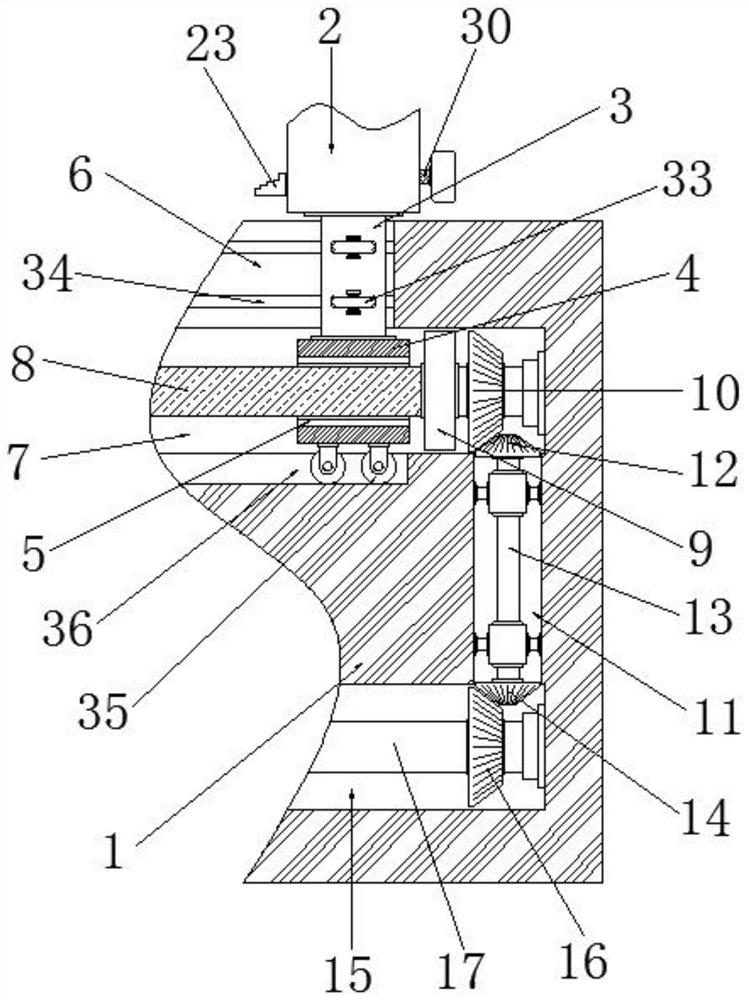
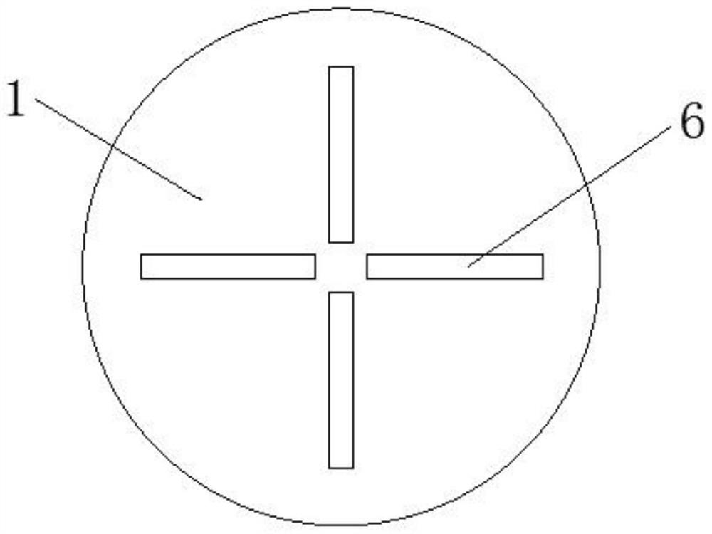
[0031] Embodiment one, such as Figure 1-6As shown, a high-precision hole slow wire fixture according to an embodiment of the present invention includes a support base 1, and the top of the support base 1 is symmetrically installed with fixed blocks 2, and the fixed blocks 2 are four symmetrically arranged. The bottom of the fixed block 2 is equipped with a connecting block 3, and the bottom of the connecting block 3 is equipped with a movable block 4, and the inside of the movable block 4 is provided with a threaded hole 5, and the support seat The position corresponding to the connecting block 3 inside the top of 1 is provided with a movable groove 6 that is compatible with the connecting block 3, and the bottom of the movable groove 6 is provided with a movable groove 6 corresponding to the movable clamping block 4. A suitable movable card slot 7, the inside of the movable card slot 7 is equipped with a threaded rod 8 that is compatible with the threaded hole 5, and the end...
Embodiment 2
[0032] Embodiment two, such as figure 1 , 2 As shown, the outer side of the connecting block 3 is symmetrically equipped with a positioning pulley 33, and the position corresponding to the positioning pulley 33 in the inside of the movable groove 6 is provided with a corresponding position corresponding to the positioning pulley 33. Adapted positioning chute one 34; the bottom of the movable block one 4 is equipped with two positioning pulleys 35 symmetrically, and the bottom of the movable clamping groove one 7 is set at the position corresponding to the two positioning pulleys 35 There is a positioning chute 2 36 that is compatible with the positioning pulley 2 35; function, can make the connecting block 3 and the movable clamping block 4 both achieve better stability, so that the fixed block 2 can achieve better stability, so that the parts can be better Step up the operation, so that it can better meet people's needs.
Embodiment 3
[0033] Embodiment three, such as figure 1 , 2 As shown, the two ends of the threaded rod 8 are equipped with a movable shaft seat 1, and the side of the movable shaft seat 1 away from the threaded rod 8 is fixedly connected with the two sides of the movable card slot 1 7 The inside of the installation groove one 11 is symmetrically equipped with a positioning bushing one, and the positioning bushing one is sleeved on the outer side of the connecting rod one 13; the connecting rod two 17 is far away from the gear five 18 One end of each is equipped with movable shaft seat 2, and one end of the connecting rod 2 17 close to the gear 5 18 is provided with a positioning shaft sleeve 2, and the movable shaft seat 2 and the positioning shaft sleeve 2 are all connected with the installation The groove two 15 is fixedly connected; the outer side of the connecting block 3 is provided with a positioning bushing three, and the positioning bushing three is fixedly connected with the inner...
PUM
 Abstract
Description
Claims
Application Information
 - R&D Engineer
- R&D Manager
- IP Professional
- Industry Leading Data Capabilities
- Powerful AI technology
- Patent DNA Extraction
Browse by: Latest US Patents, China's latest patents, Technical Efficacy Thesaurus, Application Domain, Technology Topic, Popular Technical Reports.
© 2024 PatSnap. All rights reserved.Legal|Privacy policy|Modern Slavery Act Transparency Statement|Sitemap|About US| Contact US: help@patsnap.com