
Strip line feed horn antenna applied to millimeter wave security check imaging

A technology of stripline feed and horn antenna, which is applied in the directions of antenna, antenna coupling, antenna array, etc., can solve the problems of narrow bandwidth, low isolation, and complex structure of integrated antennas, and achieve improved transceiver isolation and high isolation , the effect of simple structure

Active Publication Date: 2021-01-05
北京子兆信息技术有限公司
View PDF11 Cites 0 Cited by
  • Summary
  • Abstract
  • Description
  • Claims
  • Application Information

AI Technical Summary

Problems solved by technology

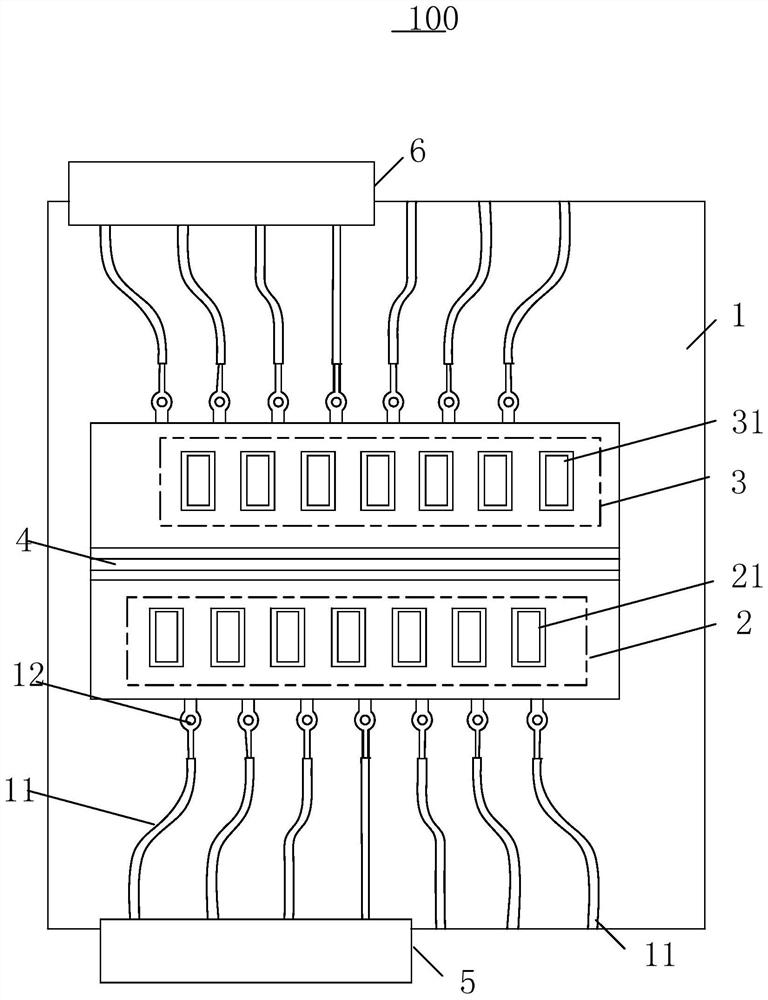
[0005] The purpose of the present invention is to overcome the problems of narrow bandwidth, low efficiency, low isolation and complex structure of the radio frequency front-end integrated antenna existing in the prior art, and to provide a A stripline-fed horn antenna applied to millimeter-wave security inspection imaging, the stripline-fed horn antenna applied to millimeter-wave security inspection imaging has the characteristics of broadband, high efficiency, high isolation, simple structure, and strong assembly reliability

Method used


Image

  • Strip line feed horn antenna applied to millimeter wave security check imaging
  • Strip line feed horn antenna applied to millimeter wave security check imaging
  • Strip line feed horn antenna applied to millimeter wave security check imaging

Examples


Embodiment Construction

[0030] Specific embodiments of the present invention will be described in detail below in conjunction with the accompanying drawings. It should be understood that the specific embodiments described here are only used to illustrate and explain the present invention, and are not intended to limit the present invention.

[0031] In the description of the present application, the terms "first" and "second" are used for descriptive purposes only, and cannot be understood as indicating relative importance, or implicitly indicating the quantity of indicated technical features. Therefore, unless otherwise specified, the features defined as "first" and "second" may explicitly or implicitly include one or more of these features; "plurality" means two or more. The term "comprising" and any variations thereof mean non-exclusive inclusion, possible presence or addition of one or more other features, integers, steps, operations, units, components and / or combinations thereof.

[0032] Also,...


PUM


Abstract

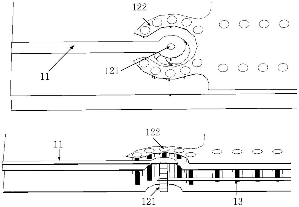
The invention relates to the technical field of antenna array design of millimeter wave security check imaging, and discloses a strip line feed horn antenna applied to millimeter wave security check imaging. According to the strip line feed horn antenna applied to millimeter wave security check imaging, a microstrip line-to-strip line structure is arranged on a printed circuit board, a choke groove is additionally formed between a transmitting antenna array and a receiving antenna array, and the microstrip line-to-strip line structure is used for realizing conversion from a microstrip line toa strip line; and the choke groove is used for suppressing interference signals outside reflection cavities of the transmitting antenna array and the receiving antenna array so as to improve the receiving and transmitting isolation. The strip line feed horn antenna applied to millimeter wave security check imaging has the characteristics of wide band, high efficiency, high isolation, simple structure and high assembly reliability.

Description

technical field [0001] The invention relates to the technical field of antenna array design for millimeter wave security inspection imaging, in particular to a strip line feed horn antenna applied to millimeter wave security inspection imaging. Background technique [0002] The millimeter-wave security imager works in the near-field area of ​​the antenna array. In order to improve the signal-to-noise ratio of the received signal, the transmission power should be increased as much as possible, and the signal isolation between the transceiver antenna arrays should be improved to avoid direct coupling of the transceiver antenna. The chain pre-stage LNA pushes saturation. In order to improve the system integration, the antenna and the RF transceiver module are designed on the same printed board, and the printed line is used to directly connect the power supply, eliminating the need for related connecting cables and RF connectors, effectively reducing the system cost. Currently ...

Claims


Application Information

Patent Timeline
IPC IPC(8): H01Q1/38H01Q1/50H01Q1/52H01Q21/00
CPCH01Q1/38H01Q1/50H01Q1/525H01Q21/0075
Inventor 孙国琳欧乃铭姚现勋
Owner 北京子兆信息技术有限公司
Learn More