Navigation signal pseudo-range deviation correction method

A deviation correction and navigation signal technology, which is applied in satellite radio beacon positioning systems, measuring devices, instruments, etc., can solve the problems that the deviation cannot be eliminated, the performance of the reference receiver and the user receiver is inconsistent, and the pseudo-range deviation of the user receiver, etc.

Pending Publication Date: 2021-01-05
NAT TIME SERVICE CENT CHINESE ACAD OF SCI
View PDF0 Cites 7 Cited by
  • Summary
  • Abstract
  • Description
  • Claims
  • Application Information

AI Technical Summary

Problems solved by technology

However, when this signal is used in GNSS differential applications, due to the inconsistency in the performance of the reference receiver and the user receiver, specifically, the difference in front-end bandwidth, code detector type and correlation interval between the reference receiver and the user receiver, the given User receivers generate pseudorange biases
like figure 1 As shown, in...

Method used


Image

  • Navigation signal pseudo-range deviation correction method
  • Navigation signal pseudo-range deviation correction method
  • Navigation signal pseudo-range deviation correction method

Examples


Embodiment Construction

[0071] In order to enable those skilled in the art to better understand that the technical solutions of the present invention can be implemented, the present invention will be further described below in conjunction with specific examples, but the given examples are only used as illustrations of the present invention, not as limitations of the present invention.

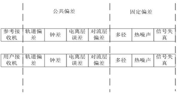
[0072] In the process of satellite navigation signal generation, propagation and reception, every link will bring distortion to the signal. For most users, the ranging deviation caused by this signal distortion will not cause serious damage to their positioning function. However, this signal is used in GNSS differential applications due to inconsistencies in the performance of the reference software receiver and the user software receiver, specifically, the reference software receiver and user software receiver front-end bandwidth, code phase detector type and correlation The intervals are different, resulting in a pse...


PUM


Abstract

The invention relates to a navigation signal pseudo-range deviation correction method. The method comprises the following steps: S1, calibrating pseudo-range deviation characteristic parameters: measuring a satellite-ground distance between a satellite and an antenna; accurately measuring the transmission time delay of a receiving terminal of the large-aperture antenna; analyzing error characteristics of pseudo-range measurement of a receiver; S2, calibrating inter-satellite difference: calibrating the time delay of a receiving channel of the receiver; measuring the inter-station distance; measuring a satellite-ground distance; carrying out synchronous measurement testing of the antenna and an omnidirectional receiving antenna; synchronously calibrating inter-satellite differences of satellite navigation signals in a visual range; synchronously calibrating the inter-satellite difference of GNSS satellites; S3, testing and verifying: analyzing the positioning error of the receiver, andverifying the correction precision of the pseudo-range measurement correction parameter; and adjusting the pseudo-range measurement correlator interval of a software receiver and the filter bandwidthkey parameters, and researching the quantitative relation between the parameters of the software receiver and the signal ranging deviation. The method has the advantages that the influence of pseudo-range deviation on distance measurement of the software receiver is weakened, and the system positioning precision is improved.

Description

technical field [0001] The invention belongs to the field of navigation signal deviation correction, and in particular relates to a navigation signal pseudo-range deviation correction method. Background technique [0002] Due to the non-ideal characteristics of satellite downlink navigation signals, the pseudo-range difference when the same receiver observes different satellite signals at the same frequency point is not equal, and the pseudo-range difference when two receivers with different technical states observe the same satellite signal at the same frequency point The distance difference values ​​are also not equal, a phenomenon known as pseudorange bias. The pseudo-range deviation is caused by the inconsistency of satellite navigation signal distortion, which directly affects the user's ranging and positioning. At present, the research on pseudo-range bias correction methods is focused on the receiver, and the influence of pseudo-range bias is mitigated by parameters ...

Claims


Application Information

Patent Timeline
IPC IPC(8): G01S19/41G01S19/39G01S19/23G01S19/44
CPCG01S19/235G01S19/41G01S19/44G01S19/396
Inventor 石慧慧卢晓春饶永南
Owner NAT TIME SERVICE CENT CHINESE ACAD OF SCI
Why Eureka
Try Eureka