
Disc brake device for automobile braking

A technology of disc brakes and automobile brakes, applied in the direction of brake types, axial brakes, brake components, etc., can solve problems such as potential safety hazards, loss, blockage, etc., and achieve the effect of guaranteeing the effect and ensuring safety

Inactive Publication Date: 2021-01-05
滁州市共赢汽车配件有限公司
View PDF0 Cites 2 Cited by
  • Summary
  • Abstract
  • Description
  • Claims
  • Application Information

AI Technical Summary

Problems solved by technology

[0003] 1. The brake disc is always exposed to the external environment, so when it is driving on a rainy day or a muddy road, some small solid particles will adhere to the surface of the brake disc, so that the brake pad and the brake disc will be pressed when braking. These small particles will wear the surface of the brake disc to a large extent during braking, resulting in a decrease in the subsequent braking effect, and there are certain potential safety hazards. At the same time, when the friction plate and the brake disc brake It will wear out the friction plate, and the friction plate will be ground with a lot of powdery small particles, which cannot be removed well only by a heat sink, and may also cause blockage, which will aggravate the wear situation
[0004] 2. Frictional braking between the friction plate and the brake disc will cause loss, which will cause the distance between the friction plate and the automatic disc to increase, so that the same braking effect will be required for subsequent braking, but it will take longer The braking path, that is, after the loss of the friction plate, it cannot automatically make up for this part of the loss, so that the braking effect is reduced. For users with high braking frequency, it is necessary to maintain and replace the friction plate frequently.

Method used


Image

  • Disc brake device for automobile braking
  • Disc brake device for automobile braking
  • Disc brake device for automobile braking

Examples


Embodiment Construction

[0024] The following will clearly and completely describe the technical solutions in the embodiments of the present invention with reference to the accompanying drawings in the embodiments of the present invention. Obviously, the described embodiments are only some, not all, embodiments of the present invention. Based on the embodiments of the present invention, all other embodiments obtained by persons of ordinary skill in the art without making creative efforts belong to the protection scope of the present invention.

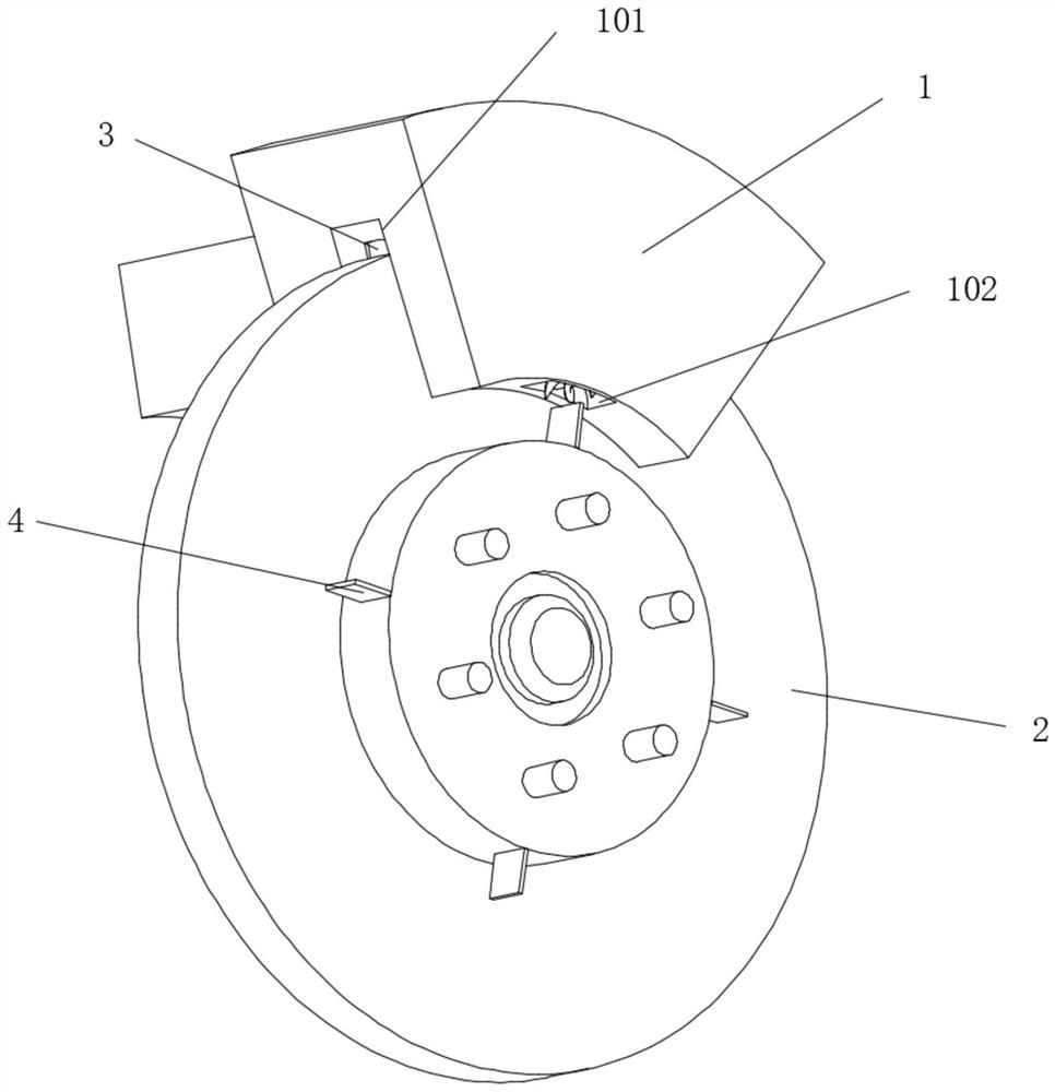
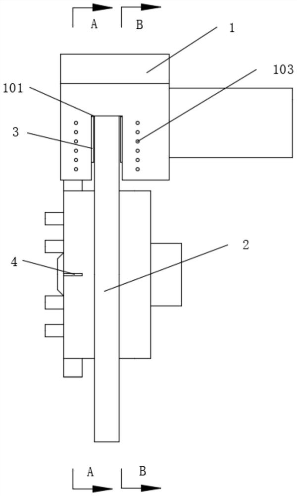
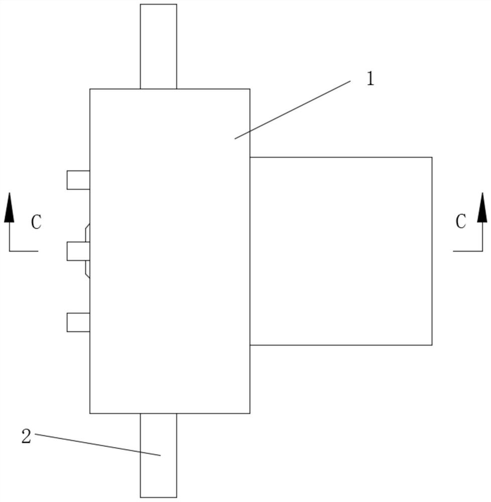
[0025] see Figure 1-9 , a disc brake device for automobile braking, comprising a brake caliper 1 and a brake disc 2, the bottom of the middle part of the brake caliper 1 is provided with a brake groove 101, and friction plates 3 are movably installed on both sides of the brake groove 101, The outer rings at both ends of the brake disc 2 are ring-shaped and uniformly fixed with rotating blades 4, and the brake caliper 1 is located in the middle of the bottom o...


PUM


Abstract

The invention relates to the technical field of machine manufacturing, and discloses a disc brake device for automobile braking. The disc brake device for automobile braking comprises a brake caliperand a brake disc, a brake groove is formed in the bottom of the middle of the brake caliper, friction plates are movably installed at the two sides of the brake groove, and rotating blades are annularly, evenly and fixedly installed at the outer rings of the two ends of the brake disc; air collecting grooves are formed in the middle positions, located at the bottoms of the two sides of the brake groove, of the brake caliper, screw rods are movably installed in the air collecting grooves, air blowing holes are evenly formed in one side of the brake caliper in a vertical strip shape, and a transmission cavity is formed in the position, located at the tops of the air collecting grooves, in the brake caliper; and a rotating shaft is movably installed at the position, close to the middle of thebrake caliper, of the top of the transmission cavity, and rotating spiral blades are movably mounted in the positions, located in the middles of the air blowing holes, of the transmission cavity. According to the disc brake device, the surface of the brake disc is kept clean through cooperation of the screw rods, the air blowing holes and other structures, the brake effect is guaranteed, meanwhile, heat dissipation is facilitated, and the service life is long.

Description

technical field [0001] The invention relates to the technical field of mechanical manufacturing, in particular to a disc brake device for automobile braking. Background technique [0002] The current car brakes are divided into two categories, one is drum brakes, and the other is disc brakes. Drum brakes are cheaper than disc brakes, but disc brakes are more convenient to work with the ABS system. It is more safe to use, so now many cars are beginning to install disc brakes, but there are still some problems in the actual use of disc brakes: [0003] 1. The brake disc is always exposed to the external environment, so when it is driving on a rainy day or a muddy road, some small solid particles will adhere to the surface of the brake disc, so that the brake pad and the brake disc will be pressed when braking. These small particles will wear the surface of the brake disc to a large extent during braking, resulting in a decrease in the subsequent braking effect, and there are ...

Claims


Application Information

Patent Timeline
IPC IPC(8): F16D55/226F16D65/00F16D65/56F16D65/847
CPCF16D55/226F16D65/0031F16D65/0068F16D65/567F16D65/847F16D2055/0016
Inventor 操龙俊
Owner 滁州市共赢汽车配件有限公司
Learn More