
Efficient and energy-saving type anti-overload hydroelectric generation equipment

A high-efficiency, energy-saving, and overload-proof technology is applied in hydropower, mechanical equipment, and electromechanical devices. It can solve problems such as the influence of water flow velocity and the generator cannot be actively adjusted, so as to improve service life, avoid overheating damage, and avoid overload damage. Effect

Inactive Publication Date: 2021-01-05
于亚美
View PDF0 Cites 2 Cited by
  • Summary
  • Abstract
  • Description
  • Claims
  • Application Information

AI Technical Summary

Problems solved by technology

[0004] The purpose of the present invention is to solve the disadvantage that the traditional generator in the prior art cannot actively adjust the flow velocity of the water body, thus affecting the power generation quality of the generator, and proposes a high-efficiency and energy-saving anti-overload hydroelectric power generation equipment

Method used


Image

  • Efficient and energy-saving type anti-overload hydroelectric generation equipment
  • Efficient and energy-saving type anti-overload hydroelectric generation equipment
  • Efficient and energy-saving type anti-overload hydroelectric generation equipment

Examples


Embodiment 1

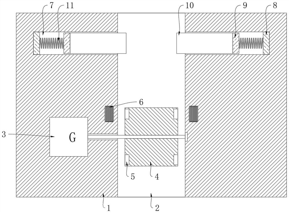
[0021] refer to figure 1 , a high-efficiency energy-saving anti-overload hydroelectric power generation equipment, including an installation platform body 1 and a generator body 3 installed in the installation platform body 1, and a circulation groove 2 for water flow is vertically opened on the installation platform body 1, and the circulation groove A plurality of fan blades 4 are installed in the 2 through the uniform rotation of the rotating shaft, and one end of the rotating shaft is connected to the input end of the generator body 3, and each fan blade 4 is symmetrically provided with a first permanent magnet block 5, and the installation platform body 1 An induction coil 6 corresponding to the first permanent magnet block 5 is symmetrically provided;

[0022] The upper side of the groove wall of the circulation groove 2 is symmetrically provided with a storage groove 7, and an electromagnet 8 is fixedly installed on the opposite groove wall of the two storage grooves 7,...

Embodiment 2

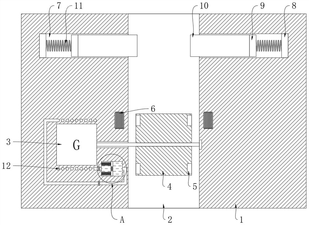
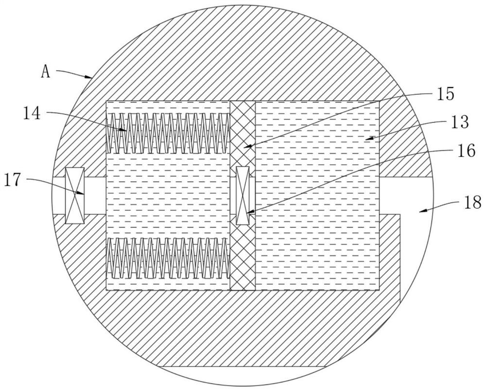
[0025] refer to Figure 2-3 , the present embodiment differs from Embodiment 1 in that: the outer cover of the generator body 3 is provided with a heat exchange coil 12; A piston block 15 made of ferromagnetic material is vertically sealed and slidably connected by a return spring 14, and the piston block 15 separates the cooling tank 13 into a driving area and a driven area;

[0026] A connecting pipe 16 is provided on the piston block 15, a one-way drain pipe 18 is connected between the driving area and the input end of the heat exchange coil 12, and a one-way drain pipe 18 is connected between the driven area and the output end of the heat exchange coil 12. The one-way liquid inlet pipe 17, the heat exchange coil 12, the cooling tank 13, the one-way liquid inlet pipe 17 and the one-way liquid discharge pipe 18 are all filled with cooling liquid, the connecting pipe 16, the one-way liquid inlet pipe 17 and the one-way The first one-way valve, the second one-way valve and th...


PUM


Abstract

The invention discloses efficient and energy-saving type anti-overload hydroelectric generation equipment which comprises an installation table body and a generator body installed in the installationtable body. A circulation groove is vertically formed in the installation table body, a plurality of fan blades are evenly and rotatably installed in the circulation groove through a rotating shaft, one end of the rotating shaft is connected with the input end of the generator body, first permanent magnet blocks are symmetrically arranged on each of the fan blades, and induction coils corresponding to the first permanent magnet blocks are symmetrically arranged in the installation table body. The fan blades are used for driving the first permanent magnet blocks to rotate, the first permanent magnet blocks rotate to enable the induction coils to generate induction current, the induction coils are matched with electromagnets, and therefore a baffle can be controlled to block the circulationgroove, so that water flow can be adjusted so as to ensure the fan blades to be at a stable rotating speed, the power generation quality of the generator body is improved, and the generator body can be prevented from being overloaded and damaged when water flow is overlarge.

Description

technical field [0001] The invention relates to the technical field of hydropower generation, in particular to a high-efficiency and energy-saving anti-overload hydropower generation equipment. Background technique [0002] With the consumption of traditional petroleum energy, energy storage around the world is becoming more and more tense. At the same time, traditional petroleum energy production often produces more harmful exhaust gas and waste, which has a greater impact on people's life and health. , so many countries have begun to develop various new energy sources to replace traditional petroleum energy sources. [0003] Hydropower resources are a renewable and clean energy, and there are many large and small rivers in our country, so hydropower resources have a good prospect. The traditional hydroelectric power generation equipment has a simple structure and directly uses water flow to impact the turbine to generate electricity. However, in actual work, the water flow...

Claims


Application Information

Patent Timeline
IPC IPC(8): F03B13/00F03B11/00H02K9/19H02K7/18
CPCF03B11/00F03B13/00H02K7/1823H02K9/19Y02E10/20
Inventor 于亚美何偏偏
Owner 于亚美
Learn More