
Carrying device for impeller and carrying method of carrying device

A technology for handling devices and impellers, which is applied in the direction of lifting devices, lifting frames, springs/shock absorbers, etc., and can solve the problems of large damage to the blade finish, low efficiency, and increased costs

Active Publication Date: 2021-01-05
中天科技集团海洋工程有限公司
View PDF6 Cites 1 Cited by
  • Summary
  • Abstract
  • Description
  • Claims
  • Application Information

AI Technical Summary

Problems solved by technology

However, the blades are easily damaged due to vibration during transportation; in addition, the hoisting operation is not only inefficient, but also damages the finish of the blades, thereby increasing the cost.

Method used


Image

  • Carrying device for impeller and carrying method of carrying device
  • Carrying device for impeller and carrying method of carrying device
  • Carrying device for impeller and carrying method of carrying device

Examples


Embodiment Construction

[0047] The technical solutions of the present invention will be clearly and completely described below through specific embodiments.

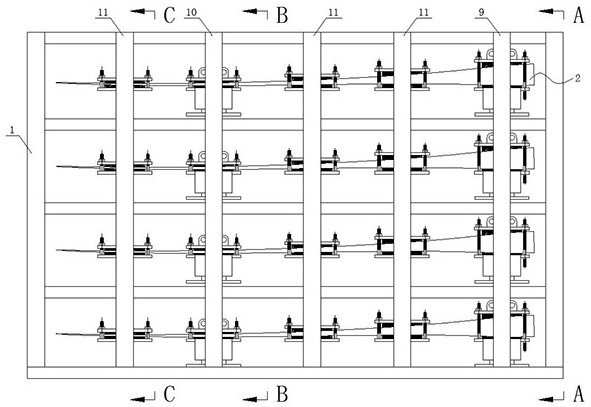
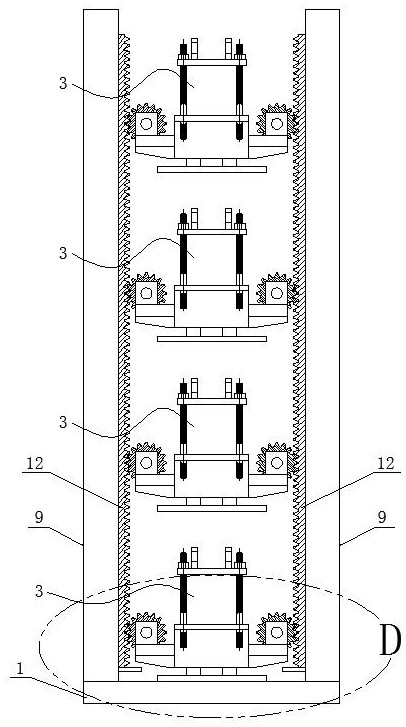
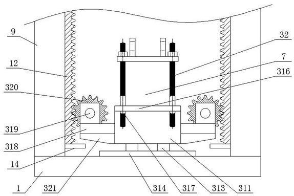
[0048] A transporting device for an impeller of the present invention includes a transporting frame 1, a blade transporting mechanism 2, a first support 9, a second support 10, a third support 11, a first rack 12, a second rack 13 and a lift Device 5; specific structure such as Figure 1~7 As shown, the transport frame 1 is a hollow cuboid frame structure placed horizontally, and four blade transport mechanisms 2 arranged horizontally and horizontally are arranged at intervals in parallel up and down inside it; The front and rear sides are also vertically symmetrically provided with first pillars 9, and the two first pillars 9 are coplanar with the front and rear sides of the transport frame 1 respectively, and integrally formed; The front and rear sides of the power point are also vertically and symmetrically provided with second pillars 10, ...


PUM


Abstract

The invention discloses a carrying device for an impeller and a carrying method of the carrying device. The carrying device comprises a carrying frame, four blade carrying mechanisms, first supportingcolumns, second supporting columns, third supporting columns, first racks, second racks and lifting devices. The four blade carrying mechanisms are arranged in the carrying frame at intervals up anddown, the first racks are vertically welded to the inner side faces of the first supporting columns, the second racks are vertically welded to the inner side faces of the second supporting columns, and each blade carrying mechanism vertically moves up and down in the carrying frame through meshing fit with the corresponding first racks and the corresponding second racks. The lifting devices are vertically arranged at the horizontal positions, opposite to the blade carrying mechanisms, of the inner side faces of the third supporting columns, and perform horizontal longitudinal movement in the direction corresponding to the blade carrying mechanisms and correspondingly lift and support the corresponding blade carrying mechanisms. The carrying device for the impeller is simple in structure and facilitates blade lifting operation, so that damage to blade finish paint is reduced, and the cost is reduced.

Description

technical field [0001] The invention relates to a conveying device, in particular to a conveying device for an impeller and a conveying method thereof. Background technique [0002] Due to the long blade length of the wind turbine and the large size of the impeller when assembled, the hub and the blade are usually transported to the installation site separately, and then the chains are used to wind the corresponding positions at both ends of the blade respectively. Through the cooperation of two cranes and suitable The spreader is used to assemble the blade and hub. However, the blades are easily damaged due to vibration during transportation; in addition, the hoisting operation is performed by chain winding, which is not only inefficient, but also greatly damages the finish paint of the blades, thereby increasing the cost. Therefore, the above problems urgently need to be solved. Contents of the invention [0003] The technical problem to be solved by the present invent...

Claims


Application Information

Patent Timeline
IPC IPC(8): B66F7/00B66F7/28F16F15/08
CPCB66F7/00B66F7/28F16F15/085
Inventor 李宏龙吴春寒沈锋郑为薛驰
Owner 中天科技集团海洋工程有限公司
Learn More