Classified crushing device for solid waste treatment
A solid waste and crushing device technology, which is applied in solid separation, grain processing, grading, etc., can solve the problems of labor consumption, inability to separate metal waste, and low efficiency, and achieve the effect of avoiding manual labor
- Summary
- Abstract
- Description
- Claims
- Application Information
AI Technical Summary
Problems solved by technology
Method used
Image

Examples
Embodiment 1
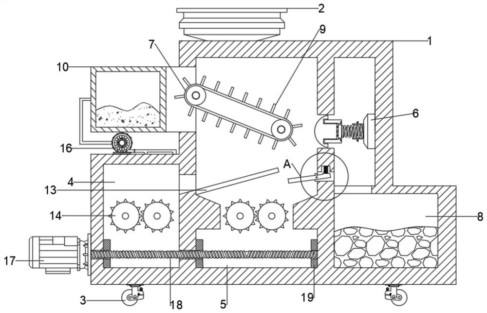
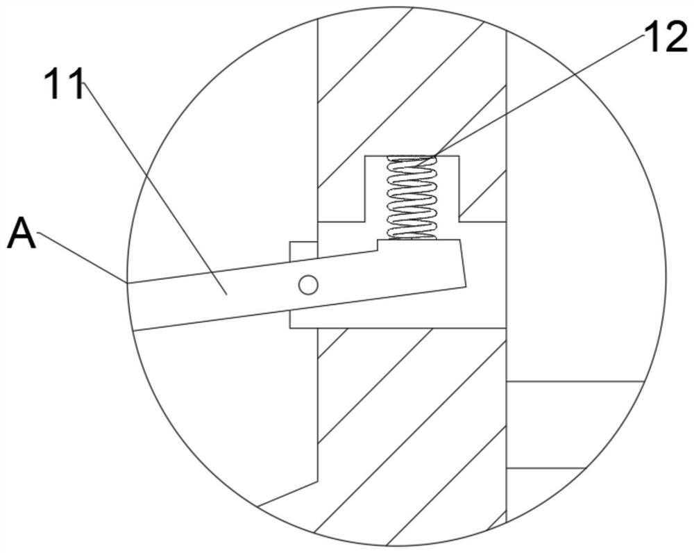
[0026] see Figure 1-6 , in the embodiment of the present invention, a sorting and crushing device for solid waste treatment includes a body 1, a feed port 2 is provided on the body 1, and a conveyor belt 7 is installed in the body 1 for rotation. Since solid waste is often mixed with Some metal garbage, and the metal garbage can be recycled and reused. In order to avoid labor-intensive manual sorting in the later stage, a metal separation assembly 6 is provided in the body 1. The metal separation assembly 6 includes a slider 601, a first electromagnet 602 and The second electromagnet 603 is slidingly fitted between the slider 601 and the first electromagnet 602, and one end of the slider 601 is elastically connected to the first electromagnet 602, and the first electromagnet 602 is provided with a second Contact 610, the first contact 609 matched with the second contact 610 is installed on the slider 601, the first spring 606 is connected between the first electromagnet 602 a...
Embodiment 2
[0029] see figure 1 and figure 2 , this embodiment makes a further improvement on the basis of embodiment 1, and the improvement content is that universal wheels 3 are symmetrically installed on the lower surface of the body 1, so as to facilitate the movement of the whole device.
[0030] Further, the conveyor belt 7 is equidistantly provided with partitions 9, so that the solid waste can be separated in batches, so as to avoid the poor separation effect caused by the overall sliding of the solid waste.
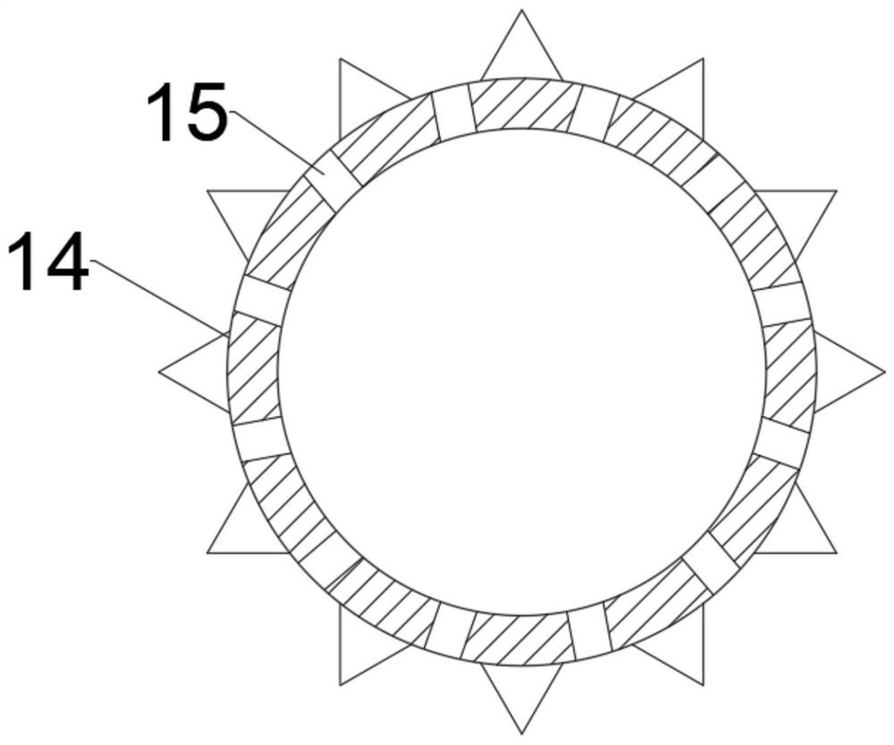
[0031]Further, the machine body 1 is provided with a crushing roller 14 for separating the separated solid waste. The inner circumference of the crushing roller 14 is integrally formed with dust suction holes 15, and the body 1 is fixed A fan 16 is installed, and one end of the fan 16 is connected with a dust box 10, which is fixedly connected between the dust box 10 and the body 1, and the other end of the fan 16 is connected with the dust suction hole 15, and the crushin...
Embodiment 1
[0033] In conjunction with embodiment 1, embodiment 2, working principle of the present invention is:
[0034] When using the present invention, when solid waste is poured into the machine body 1 through the feed port 2, the solid waste is conveyed by the conveyor belt 7, and when the metal waste is close to the slider 601, through the action of the first electromagnet 602, Thereby absorbing the metal solid waste, and making the slider 601 squeeze before the first electromagnet 602, so that the first contact 609 contacts the second contact 610, so that the second electromagnet 603 is energized and works, thereby Attract the first electromagnet 602 to move towards the second electromagnet 603, so that the main ejector rod 607 is inserted into the slot 605, so that the auxiliary ejector rod 608 is in conflict with the conductive rod 6011, so that the conductive rod 6011 is separated from the conductive block 6012, so that the second An electromagnet 602 is de-energized, so that ...
PUM
 Abstract
Description
Claims
Application Information
 - R&D
- Intellectual Property
- Life Sciences
- Materials
- Tech Scout
- Unparalleled Data Quality
- Higher Quality Content
- 60% Fewer Hallucinations
Browse by: Latest US Patents, China's latest patents, Technical Efficacy Thesaurus, Application Domain, Technology Topic, Popular Technical Reports.
© 2025 PatSnap. All rights reserved.Legal|Privacy policy|Modern Slavery Act Transparency Statement|Sitemap|About US| Contact US: help@patsnap.com