
Servo valve unit and machine

A servo valve, unit main body technology, applied in servo motors, servo meter circuits, servo motor components, etc., can solve problems such as reducing and unavoidable compressibility

Active Publication Date: 2021-01-01
EISHIN GIKEN
View PDF11 Cites 0 Cited by
  • Summary
  • Abstract
  • Description
  • Claims
  • Application Information

AI Technical Summary

Problems solved by technology

The disadvantages of the air pressure method are as mentioned above, but none of them are fundamental disadvantages
In the case of air servo, compressibility cannot be avoided, but the friction of the working cylinder can be reduced to the limit by design

Method used


Image

  • Servo valve unit and machine
  • Servo valve unit and machine
  • Servo valve unit and machine

Examples


Embodiment Construction

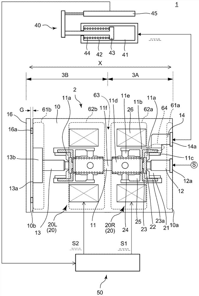
[0050] figure 1 A servo valve unit 2 and an air pressure control device 1 using the servo valve unit 2 according to one embodiment of the present invention are shown. The pneumatic control device 1 has a servo valve unit 2 , a pneumatic cylinder 40 and a controller 50 . The servo valve unit 2 has a valve body 10 formed with hollow spaces such as a common flow path 11 , a supply flow path 12 , an exhaust flow path 13 , and a drive flow path 14 . The unit main body 10 may be an assembly of a plurality of parts made of metal or plastic.

[0051] One end of the supply flow path 12 is connected to the common flow path 11 via a first valve portion 20R capable of pulse-like opening and closing based on the first electric pulse S1 . The other end of the supply channel 12 may have a connection portion (joint, etc.) 12a for connecting to a high-pressure air source such as a compressor for supplying high-pressure air S, an air tank, or the like. The connecting portion 12a may be form...


PUM


Abstract

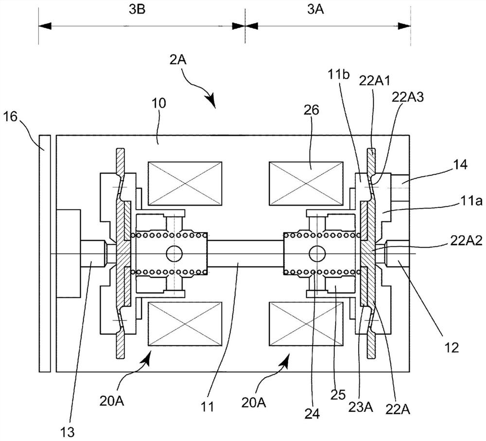
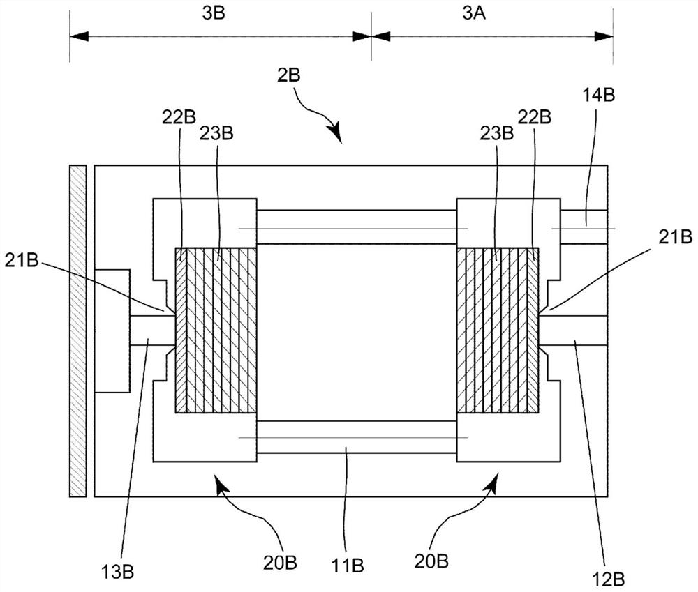
A servo valve unit (20) is provided with a unit body (10) having a first end section (61a) and a second end section (61b); a first valve part (20R); a second valve part (20L); a first seal member (22)that opens and closes the first valve part (20R); a second seal member (22) that opens and closes the second valve section (20L); a first drive mechanism that drives the first seal member (22) by means of a first electric pulse (S1); a second drive mechanism that drives the second seal member (22) by means of a second electric pulse (S2); a supply flow path (12) extending between the first end section (61a) and the first valve section (20R); an exhaust flow path (13) extending between the second end (61b) and the second valve part (20L); a common flow path (11) connected to the supply flow path (12) via a first valve part (20R) and to the exhaust flow path (13) via a second valve part (20L); and a drive flow path (14) connected to the pneumatic actuator (40).

Description

technical field [0001] The present invention relates to a servo valve unit, in particular to a servo valve unit for driving a pneumatic cylinder used in a humanoid robot and a machine using the servo valve unit. Background technique [0002] Many large companies and talented researchers have conducted research on robots for at least 50 years, but practical humanoid robots that can actually replace humans at disaster sites, nursing sites, and homes have not yet been realized. [0003] (Conditions for realization of humanoid robot) [0004] In order to realize a humanoid robot, it is necessary to design a plurality of actuators and their associated parts corresponding to the number of joints with the same weight as a human being and accommodate them in a volume similar to that of a human being, and each actuator is required to have a function corresponding to the work. of powerful power. [0005] (drive mode) [0006] There are three types of actuators: electric, hydraulic,...

Claims


Application Information

Patent Timeline
Patent Type & Authority Applications(China)
IPC IPC(8): F15B9/03F15B9/09
CPCF15B13/0405F15B13/044F15B2211/30575F15B2211/328F15B2211/8855F15B2211/7052F15B2211/7656F15B2211/6336F15B2211/6656F15B9/03F15B9/09F16K31/42F16K11/22
Inventor 久保几营
Owner EISHIN GIKEN
Learn More