Three-degree-of-freedom foldable parallel motion platform with closed-loop dual-drive sub-chain
A dual-drive, degree-of-freedom technology, applied in the testing of mechanical components, testing of machine/structural components, instruments, etc., can solve the problems of small driving output stroke and limited working space of the mechanism, and achieve the expansion ratio and guarantee Mechanism stiffness and dynamic performance, the effect of increasing flexibility
- Summary
- Abstract
- Description
- Claims
- Application Information
AI Technical Summary
Problems solved by technology
Method used
Image
Examples
Embodiment 1
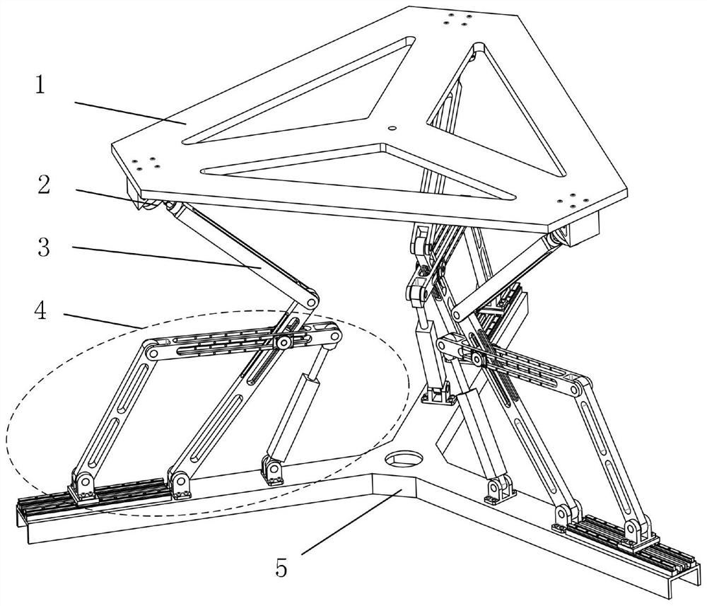
[0039] Such as figure 1 , 4 As shown, the first drive assembly of the slide plate type includes a guide rail 4-1, a slider 4-2 and a transmission rod 4-4, the guide rail 4-1 is installed on the herringbone mounting frame 5, and the slide The block 4-2 is slidably connected on the guide rail 4-1, and one end of the slide block 4-2 and the transmission rod 4-4 is connected together by the first rotating pair 3, and the end of the transmission rod 4-4 The other end is connected with one end of the linkage rod 4-6 through the second rotating pair 4-5; when working, the slider 4-2 can move horizontally along the guide rail 4-1, and the transmission rod 4-4 can move around the first The axis of the rotating pair 3 rotates, and the second rotating pair 4-5 acts as a rotating shaft to generate a rotating motion between the linkage rod 4-6 and the transmission rod 4-4. Specifically, the herringbone installation frame 5, slider 4-2, transmission rod 4-4, linkage rod 4-6, push rod 4-8 ...
Embodiment 2
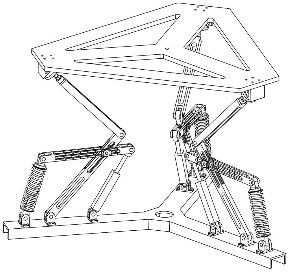
[0041] Such as image 3 , 8 As shown, the spring type first drive assembly includes a spring damper 4-20, one end of the spring damper 4-20 is installed on the herringbone mounting frame 5 through the ninth rotating pair 4-19, the The other end of the spring damper 4-20 is connected with one end of the linkage rod 4-6 through the tenth rotating pair 4-21. Compared with Embodiment 1, this embodiment has a larger working space; when working, the bottom of the spring damper 4-20 can rotate around the ninth rotating pair 4-19, and at the same time, the spring damper 4-20 can rotate around the ninth rotating pair 4-19. The cylinder pushing the push rod of 20 can drive the tenth revolving pair 4-21 to realize the movement of the up and down positions, and other linkage processes are the same as in embodiment 1. Specifically, the herringbone installation frame 5, the spring damper 4-20 (the damper includes a cylinder and a push rod), the linkage rod 4-6, the push rod 4-8 and the dr...
Embodiment 3
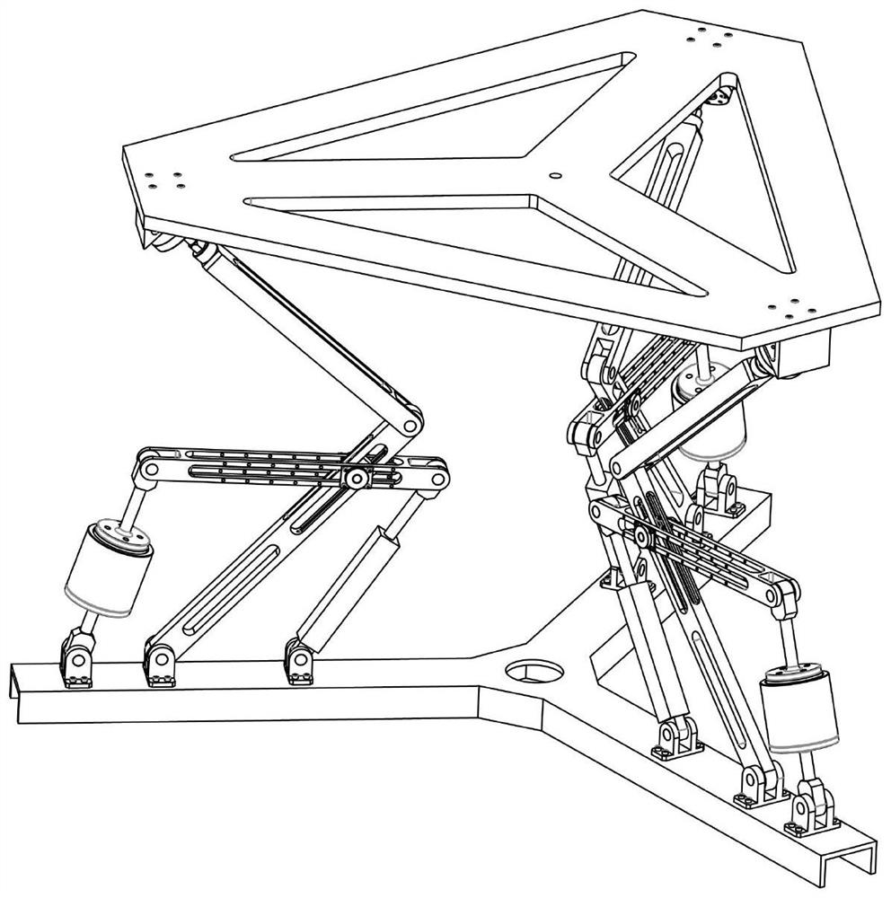
[0043] Such as figure 2 , 7 As shown, the actuator-type first drive assembly includes an actuator cylinder 4-16 and an actuator push rod 4-17, and the actuator cylinder 4-16 passes through the seventh rotating pair 4- 15 is installed on the herringbone mounting frame 5, the actuator push rod 4-17 is connected to the actuator cylinder 4-16 and is located at the upper part, and the top end of the actuator push rod 4-17 The eighth rotating pair 4-18 is connected to one end of the linkage rod 4-6; when working, the bottom of the actuator cylinder 4-16 can rotate around the seventh rotating pair 4-15, and at the same time, The actuator cylinder 4-16 pushes the actuator push rod 4-17 to drive the eighth revolving pair 4-18 to move up and down, and other linkage processes are the same as in Embodiment 1. Specifically, the herringbone mounting frame 5, the actuator cylinder 4-16, the actuator push rod 4-17, the linkage rod 4-6 push rod 4-8, and the driving cylinder 4-9 form a plane...
PUM
 Abstract
Description
Claims
Application Information
 - Generate Ideas
- Intellectual Property
- Life Sciences
- Materials
- Tech Scout
- Unparalleled Data Quality
- Higher Quality Content
- 60% Fewer Hallucinations
Browse by: Latest US Patents, China's latest patents, Technical Efficacy Thesaurus, Application Domain, Technology Topic, Popular Technical Reports.
© 2025 PatSnap. All rights reserved.Legal|Privacy policy|Modern Slavery Act Transparency Statement|Sitemap|About US| Contact US: help@patsnap.com


