
Silk thread winding roller for textile machinery

A technology of textile machinery and silk thread, which is applied in the field of silk thread winding rods for textile machinery, and can solve problems such as inconvenient use, manual control of thread, and inability to dissipate heat and ventilate

Inactive Publication Date: 2021-01-01
芜湖腾飞信息科技有限公司
View PDF1 Cites 1 Cited by
  • Summary
  • Abstract
  • Description
  • Claims
  • Application Information

AI Technical Summary

Problems solved by technology

[0005] In order to solve the above technical problems, the present invention provides a silk winding roller for textile machinery, to solve the problem that the existing textile thread winding roller cannot assist the thread to ventilate, keep the thread dry, or keep the thread dry when the thread is wet or temperature. Heat dissipation and ventilation are required for high winding, and when the existing textile thread winding rollers are used, when the thread needs to be collected, the thread end cannot be fixed and wound conveniently, and it usually requires manpower to control the winding of the thread end, which is inconvenient to use

Method used

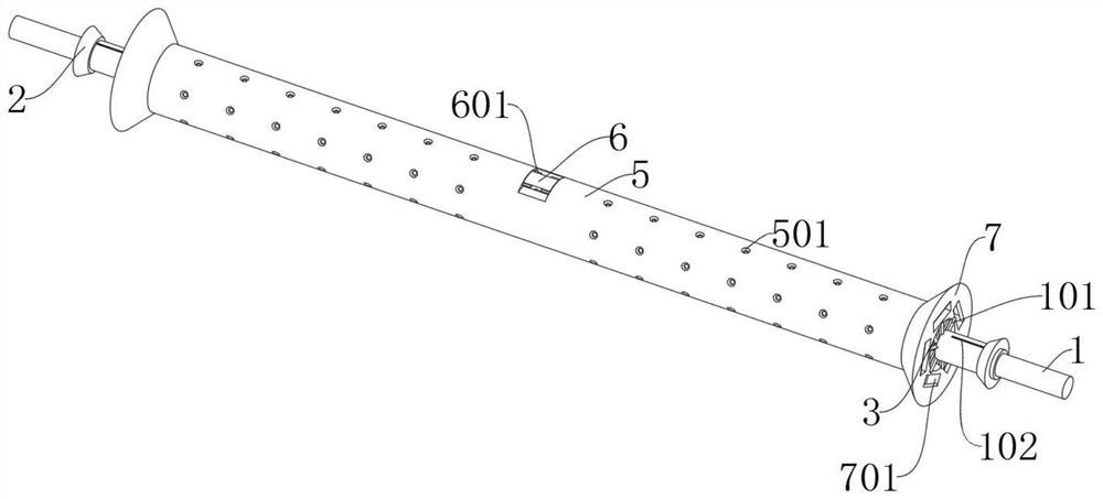
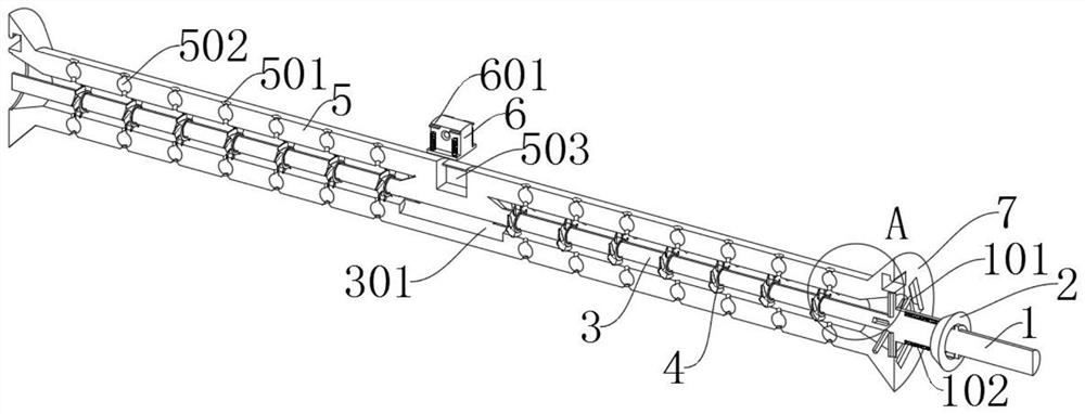
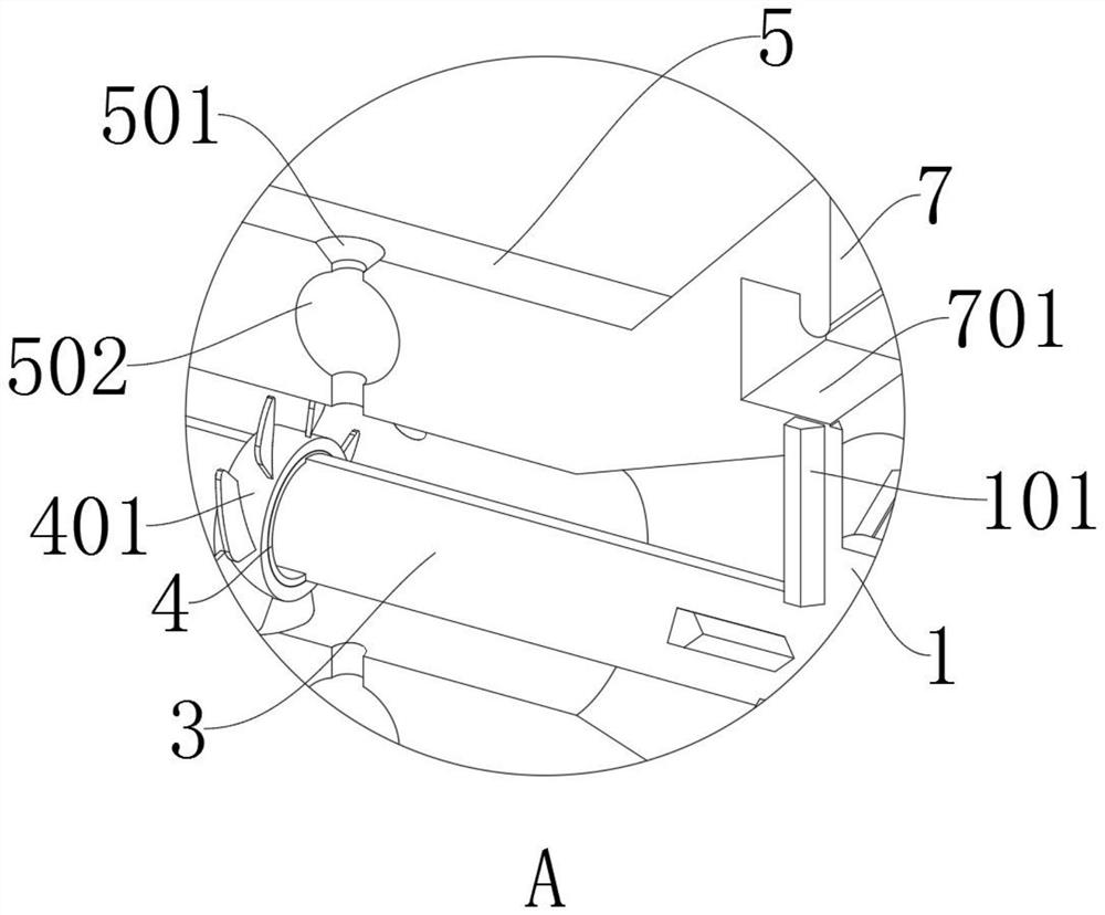

Image

  • Silk thread winding roller for textile machinery
  • Silk thread winding roller for textile machinery
  • Silk thread winding roller for textile machinery

Examples


Embodiment

[0035] as attached figure 1 to attach Figure 9 Shown:

[0036] The invention provides a thread winding roller for textile machinery, which includes a main body 1, a top block 2, an inner rod 3, a mounting part 4, a rotating roller 5, a moving part 6 and a guide part 7; the main body 1 is a cylindrical structure with a protrusion in the middle ; The top block 2 is set on the outside of the main body 1, and the guide rod 201 of the top block 2 is inserted into the inside of the guide groove 102, and the side of the guide rod 201 is connected to the inside of the guide groove 102; the inner rod 3 is in the main body 1 and the two ends of the inner rod 3 are connected to the inner end of the main body 1 through a fixed connection; the inside of the mounting part 4 is connected to the outside of the inner rod 3 through a fixed connection, and the mounting parts 4 are evenly arranged on the The two ends of the inner rod 3; the guide 7 are fixedly connected to the two ends of the ...


PUM


Abstract

The invention provides a silk thread winding roller for textile machinery, and relates to the technical field of winding rollers. The problems that when an existing textile silk thread winding rolleris used, silk threads cannot be assisted in ventilation and cannot be kept dry, and heat dissipation and ventilation cannot be conducted when the silk threads are wound in a damp or high temperature state are solved. The silk thread winding roller comprises a main body and an ejector block; the main body is of a cylindrical structure with a convex middle part; and the ejector block sleeves the outer side of the main body, a guide rod of the ejector block is inserted into a guide groove, and the side edge of the guide rod is connected with the interior of the guide groove. A rotating roller isused for directly winding the silk threads, so that the silk threads can be wound in a rotating mode after the rotating roller is installed, when the silk threads are wound, if the silk threads are damp or high in temperature, wind passes through the interior of the rotating roller and then makes contact with the silk threads through inner holes and outer holes, the wind can assist in heat dissipation or ventilation of the silk threads, and then the silk threads can be kept dry, and use of the silk threads is not affected.

Description

technical field [0001] The invention belongs to the technical field of winding rollers, and more specifically relates to silk winding rollers for textile machinery. Background technique [0002] When weaving, it is usually necessary to use a winding roller to wind the textile thread so that the thread can be collected or used. [0003] For example, the application number: CN201811196291.0 relates to a silk winding roller for textile machinery, including a fixed installation rod, a controllable deceleration winding roller internal device, a left protective block, a winding roller body, a right tap protection block, and a power belt connecting rod , anti-slip plate, connecting mounting block, the right side of the fixed mounting rod is connected with the left side of the internal device of the winding roller with controllable deceleration by electric welding, and the axis of the fixed mounting rod is connected with the left side of the internal device of the winding roller wit...

Claims


Application Information

Patent Timeline
IPC IPC(8): B65H75/28B65H75/18B65H75/14
CPCB65H75/14B65H75/18B65H75/28B65H2701/31
Inventor 王和
Owner 芜湖腾飞信息科技有限公司
Learn More