
Belt assembly line

An assembly line and belt technology, applied in the field of assembly line, can solve the problems of increased thermal friction in the contact area, easy to increase the belt wear degree, unfavorable belt heat dissipation, etc., so as to reduce the thermal wear degree, promote heat dissipation, and reduce the effect of thermal friction area.

Inactive Publication Date: 2021-01-01
徐小林
View PDF0 Cites 2 Cited by
  • Summary
  • Abstract
  • Description
  • Claims
  • Application Information

AI Technical Summary

Problems solved by technology

[0003] Due to the imperfect technology of the existing belt assembly line, the drum is a conventional cylinder, so that the belt and the drum are in surface contact, and the contact area is large. The belt will have thermal friction with the drum during long-term transportation, and the surface contact is not conducive to the belt. Heat dissipation, which will easily increase the wear of the belt, and the large contact area will increase thermal friction, which will aggravate the aging of the belt

Method used


Image

  • Belt assembly line
  • Belt assembly line
  • Belt assembly line

Examples


Embodiment 1

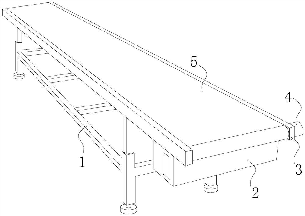
[0035] see Figure 1-4 , the present invention provides a belt assembly line technical solution: its structure includes a support frame 1, a control box 2, a limit guard 3, a motor 4, a belt 5, a first roller 6, a second roller 7, the support frame 1 Connect the limit guard plate 3, the limit guard plate 3 is provided with two pieces, a belt 5 is arranged between the two limit guard plates 3, one end of the belt 5 is movably matched with the first roller 6, and the other end is Matched with the second roller 7, the second roller 7 is connected to the motor 4, the motor 4 is connected to the limit guard plate 3, and the support frame 1 is also connected to the control box 2.

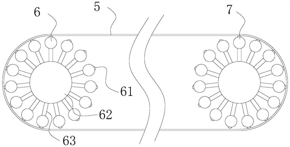
[0036] The first drum 6 includes a sub-cylinder 61, a central shaft 62, and a connecting plate 63. The fifteenth equal parts of the central shaft 62 are provided with connecting plates 63, and the connecting plate 63 is far away from the side of the central axis 62. Both of them are fixed with sub-cylind...

Embodiment 2

[0041] see Figure 1-9 , the present invention provides a belt assembly line technical solution: its structure includes a support frame 1, a control box 2, a limit guard 3, a motor 4, a belt 5, a first roller 6, a second roller 7, the support frame 1 Connect the limit guard plate 3, the limit guard plate 3 is provided with two pieces, a belt 5 is arranged between the two limit guard plates 3, one end of the belt 5 is movably matched with the first roller 6, and the other end is Matched with the second roller 7, the second roller 7 is connected to the motor 4, the motor 4 is connected to the limit guard plate 3, and the support frame 1 is also connected to the control box 2.

[0042] The first drum 6 includes a sub-cylinder 61, a central shaft 62, and a connecting plate 63. The fifteenth equal parts of the central shaft 62 are provided with connecting plates 63, and the connecting plate 63 is far away from the side of the central axis 62. Both are fixed with a sub-tube 61, the...


PUM


Abstract

The invention discloses a belt assembly line. The belt assembly line structurally comprises a supporting frame, a control box, limiting protection plates, a motor, a belt, a first roller and a secondroller, wherein the supporting frame is connected with the limiting protection plates, the number of the limiting protection plates is two, the belt is arranged between the two limiting protection plates, one end of the belt movably matches with the first roller, the other end of the belt matches with the second roller. Compared with the prior art, the belt assembly line has the beneficial effectsthat a novel roller is formed by combining a branch roller, a center shaft and a connecting plate and is greatly different from a traditional cylindrical roller, so that the belt is in linear contactwith the novel roller, the area contact of the traditional roller and the belt are abandoned, the contact area of the roller and the belt can be greatly reduced, the heat friction area can be reduced, the heat abrasion degree of the belt can be reduced, air circulation is facilitated through a formed ventilation channel and a formed heat dissipation channel, heat dissipation of the belt is betterfacilitated, a transverse column is detachably installed, only the transverse column need to be replaced, and the cost is reduced.

Description

technical field [0001] The invention relates to the technical field of assembly line, in particular to a belt assembly line. Background technique [0002] The belt assembly line is a kind of assembly line, which occupies a large market, so various large enterprises have transformed it one after another, using assembly lines to save labor and improve work efficiency. It can transport a wide variety of materials, not only can transport various bulk materials, but also can transport various light-weight products such as cartons and packaging bags, and can also be used to transport goods at the cash register of large supermarkets. It has a wide range of uses. [0003] Due to the imperfect technology of the existing belt assembly line, the drum is a conventional cylinder, so that the belt and the drum are in surface contact, and the contact area is large. The belt will have thermal friction with the drum during long-term transportation, and the surface contact is not conducive to...

Claims


Application Information

Patent Timeline
Patent Type & Authority Applications(China)
IPC IPC(8): B65G15/32B65G23/04B65G23/22B65G39/02
CPCB65G15/32B65G23/04B65G23/22B65G39/02
Inventor 徐小林
Owner 徐小林
Learn More