
Drainage tube

A technology of drainage tube and suction tube, applied in the field of drainage tube, can solve the problems of trouble and pain of patients, inability to drain fluid and so on.

Active Publication Date: 2021-01-01
重庆市妇幼保健院
View PDF10 Cites 0 Cited by
  • Summary
  • Abstract
  • Description
  • Claims
  • Application Information

AI Technical Summary

Problems solved by technology

[0003] At present, most of the drainage tubes of chest cavity and abdominal cavity are mostly single-tube type in clinical practice. During drainage, the suction tube is extended into the fluid accumulation in the human body to drain it. However, because the chest cavity and abdominal cavity are not smooth inner cavities , all the effusions in the pleural cavity will not naturally converge into one place. If a single-tube drainage tube is used, all the effusions in the pleural cavity cannot be drained at one time, and medical workers have to constantly change the position of the suction tube. Re-drainage in the same way will inevitably cause trouble and pain to patients and medical workers

Method used


Image

  • Drainage tube
  • Drainage tube
  • Drainage tube

Examples


Embodiment Construction

[0026] Embodiments of the technical solutions of the present invention will be described in detail below in conjunction with the accompanying drawings. The following examples are only used to illustrate the technical solutions of the present invention more clearly, and therefore are only examples, rather than limiting the protection scope of the present invention.

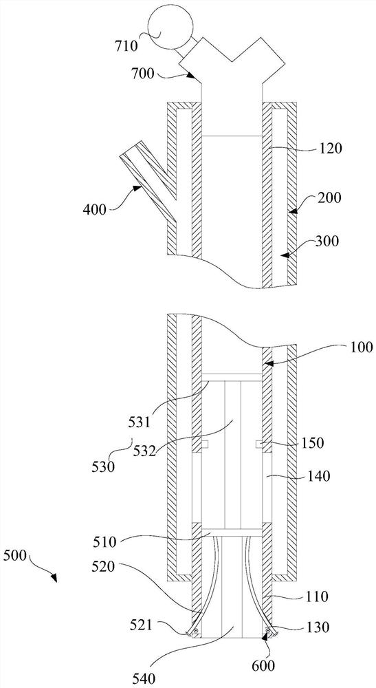
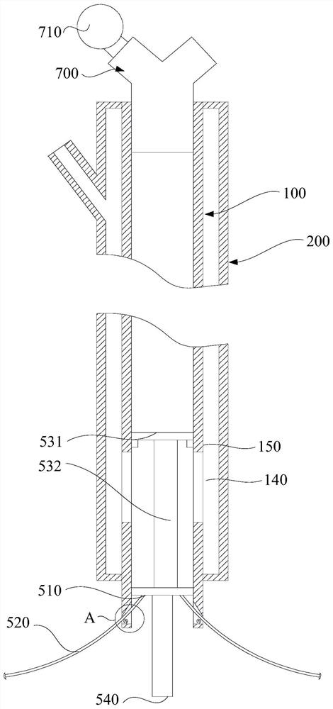
[0027] See Figure 1 to Figure 4 , the present invention provides a drainage tube, including an inner tube 100, an outer tube 200, a side tube 400 and a suction assembly 500, for drainage of body fluid.

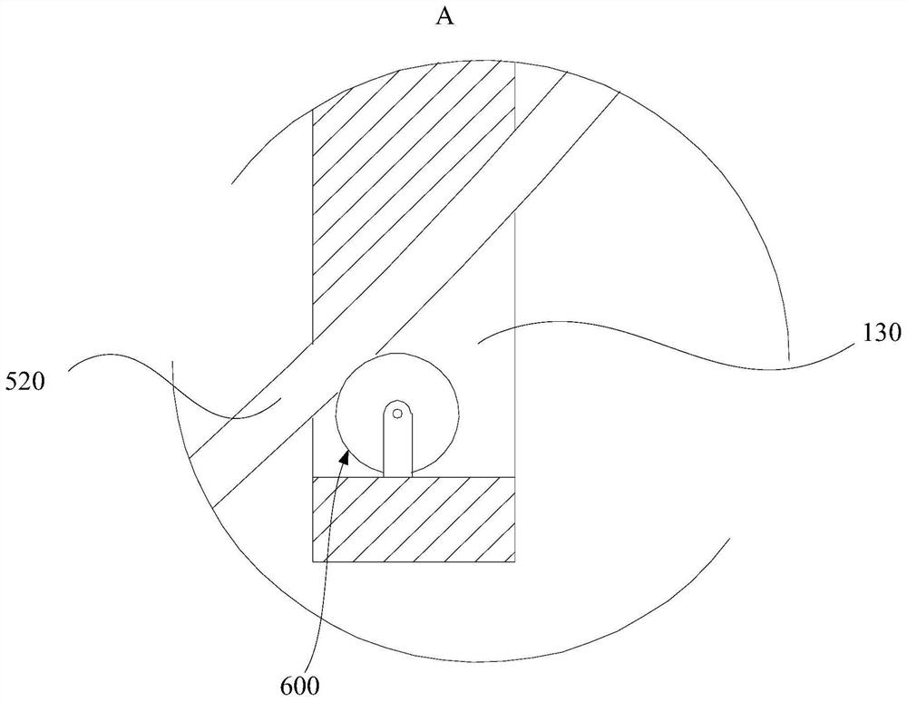
[0028] See figure 1 and figure 2 Specifically, both ends of the inner tube 100 are open. One end of the inner tube 100 is an insertion end 110 , and the other end is an exposed end 120 . The insertion end 110 is used for insertion into the body, and the exposed end 120 is exposed outside the body. The insertion end 110 is provided with a plurality of through holes 130 communicated with the inner cavity at in...


PUM


Abstract

The invention discloses a drainage tube. The drainage tube comprises an inner tube, an outer tube, a side tube and a suction assembly; the two ends of the inner tube are open, one end of the inner tube is an insertion end, and the other end is an exposed end; the inner tube is sleeved with the outer tube, the two ends of the outer tube are connected with the outer wall of the inner tube, and a containing cavity is formed between the outer tube and the inner tube; the side tube is arranged on the side wall of the outer tube, and the side tube communicates with the containing cavity; the suctionassembly comprises a mounting plate, suction tubes and a driving assembly; the mounting plate is slidably located in the inner tube; a plurality of leakage holes are formed in the mounting plate; thesuction tubes are elastic, the number of the suction tubes is multiple, and each suction tube penetrates through a through hole from the outside of the insertion end, then is connected to the mounting plate and can slide in the inner tube; the driving assembly is arranged on the mounting plate; and the mounting plate can be driven to slide in the inner tube. According to the drainage tube, effusion at multiple positions in a human body can be drained, so that the pain of a patient is relieved, and the workload of medical workers is reduced.

Description

technical field [0001] The invention relates to a drainage tube. Background technique [0002] Drainage tube is a medical device used for clinical surgical drainage to guide pus, blood, and liquid accumulated between human tissues or body cavities to the outside of the body to prevent postoperative infection and promote wound healing. There are many types of surgical drainage tubes used clinically, some are used for catheterization, some are used for wounds, and they are used in the chest cavity, brain cavity, gastrointestinal tract, and biliary tract. The purpose of surgical drainage is to guide the pus, blood, and fluid accumulated between human tissues or body cavities to the outside of the body, so as to prevent postoperative infection and affect wound healing. [0003] At present, most of the drainage tubes of chest cavity and abdominal cavity are mostly single-tube type in clinical practice. During drainage, the suction tube is extended into the fluid accumulation in ...

Claims


Application Information

Patent Timeline
Patent Type & Authority Applications(China)
IPC IPC(8): A61M25/14
CPCA61M25/0023A61M2025/0002A61M2205/3331
Inventor 华露池余刚刘丹丹
Owner 重庆市妇幼保健院
Learn More