
All-solid-state DC circuit breaker

A DC circuit breaker, all-solid-state technology, applied in circuit devices, emergency protection circuit devices, emergency protection devices with automatic disconnection, etc., can solve the problems of large turn-off overvoltage and long turn-off time

Pending Publication Date: 2020-12-29
CSR ZHUZHOU ELECTRIC LOCOMOTIVE RES INST
View PDF10 Cites 1 Cited by
  • Summary
  • Abstract
  • Description
  • Claims
  • Application Information

AI Technical Summary

Problems solved by technology

[0003] In view of the above problems, the present disclosure provides an all-solid-state DC circuit breaker, which solves the technical problems of long turn-off time and large turn-off overvoltage of existing DC circuit breakers

Method used


Image

  • All-solid-state DC circuit breaker
  • All-solid-state DC circuit breaker
  • All-solid-state DC circuit breaker

Examples


Embodiment 1

[0057] This embodiment provides a circuit topology of an all-solid-state DC circuit breaker.

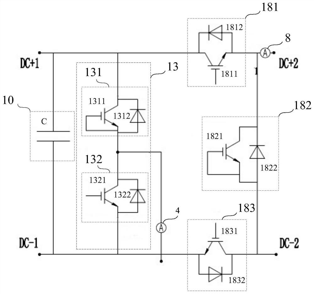
[0058] figure 1 It is a circuit diagram of a circuit topology of an all-solid-state DC circuit breaker shown in an exemplary embodiment of the present disclosure. see figure 1 , the circuit topology includes a switch module (not marked in the figure), a current detection module (not marked in the figure) and a chopping current sensor 4 .

[0059] A switch module, which is electrically connected between the first converter (not shown in the figure) and the second converter (not shown in the figure), and is used to control the connection between the first converter and the second converter The circuit breaks between. In addition, the switch module can also be electrically connected between the converter and the load or the power supply, and is used to control the on-off of the circuit between the converter and the load or the power supply. This embodiment takes the electrical conne...

Embodiment 2

[0076] On the basis of Embodiment 1, this embodiment provides an all-solid-state DC circuit breaker.

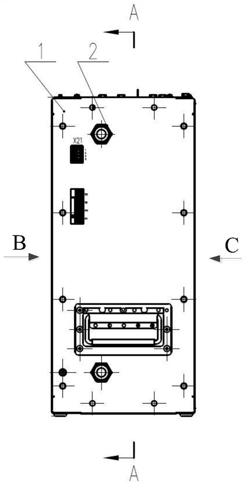
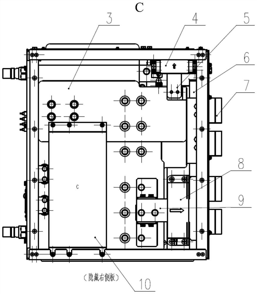
[0077] The structure of the all-solid-state DC circuit breaker is as follows: Figure 2 to Figure 6 As shown, the all-solid-state DC circuit breaker includes a switch module (not marked in the figure), a current detection module (not marked in the figure), a drive module (not marked in the figure), a temperature monitoring module (not marked in the figure), and a circuit breaker housing Body 1, quick connector 2, low-sensitivity busbar 3, chopper current sensor 4, chopper outlet bar 5, quick plug busbar support epoxy 6, quick plug 7, DC side current sensor connection busbar 9, insulation fixing plate (not shown in the figure), heat dissipation module 11, power socket 12, chopper unit detection board 14, temperature sensor 16, circuit breaker IGBT detection board 17, low-sensitivity busbar upper outlet busbar DC+1 supporting epoxy 19, The low-sensitivity busbar upper outlet b...


PUM


Abstract

The invention provides an all-solid-state DC circuit breaker, and the circuit breaker comprises a switching module which is electrically connected between a converter and a load; a current detection module which is electrically connected between the switch module and the load and is used for detecting the current input into the load; a pulse distribution module, wherein a first input end of the pulse distribution module is electrically connected with an external control system, a second input end of the pulse distribution module is electrically connected with a signal output end of the currentdetection module, and the pulse distribution module is used for outputting a first control signal when receiving an external control signal sent by the external control system, and judging the received current corresponding to the electric signal output by the current detection module so as to output a second control signal when the received current corresponding to the electric signal output bythe current detection module exceeds a preset threshold value; and a driving module which is used for controlling the switch module to act according to the control signal output by the pulse distribution module. The all-solid-state direct-current circuit breaker provided by the invention is compact in structure, short in turn-off time and small in turn-off overvoltage.

Description

technical field [0001] The disclosure relates to the field of electronic power control, in particular to an all-solid-state DC circuit breaker. Background technique [0002] With the development of DC power transmission and distribution technology, DC micro-grid and smart grid technology, DC circuit breakers, as switching devices that carry, switch DC operating branch currents, and various fault currents within a specified time, are important for improving DC power distribution systems. An important means of stability, reliability and flexibility. Expansion of system failure can be prevented. Different from AC, DC current has no zero-crossing point, which brings arc extinguishing problems, overvoltage problems and energy absorption problems during the shutdown process to circuit breakers, which has also become a technical bottleneck in the development of DC circuit breakers. The operating time of the traditional mechanical DC circuit breaker is as long as tens of milliseco...

Claims


Application Information

Patent Timeline
Patent Type & Authority Applications(China)
IPC IPC(8): H03K17/082H02H3/087
CPCH03K17/0828H02H3/087
Inventor 窦泽春黄南刘少奇邹扬举罗文广钱正彦
Owner CSR ZHUZHOU ELECTRIC LOCOMOTIVE RES INST
Learn More