
Power cable, photoelectric composite cable, communication optical cable and optical fiber ribbon

A power cable, integrated technology, applied in the direction of power cables, power cables including optical transmission components, insulated cables, etc., can solve the problems of large casing size, inflexible application, and difficult to peel off

Inactive Publication Date: 2020-12-29
CHANGSHU BAILIAN PHOTOELECTRIC TECH CO LTD
View PDF3 Cites 3 Cited by
  • Summary
  • Abstract
  • Description
  • Claims
  • Application Information

AI Technical Summary

Problems solved by technology

[0004] In the prior art, the layer-twisted ribbon optical cable adopts a layered structure of optical fiber ribbons, the size of the sleeve is large, it is not easy to peel off, the cost is high, and it is not convenient for multi-turn expansion
In the prior art middle-layer twisted cable, when the casing is multi-turned, the combination of inner and outer layers is single, and the application is inflexible

Method used


Image

  • Power cable, photoelectric composite cable, communication optical cable and optical fiber ribbon
  • Power cable, photoelectric composite cable, communication optical cable and optical fiber ribbon
  • Power cable, photoelectric composite cable, communication optical cable and optical fiber ribbon

Examples


Embodiment 1

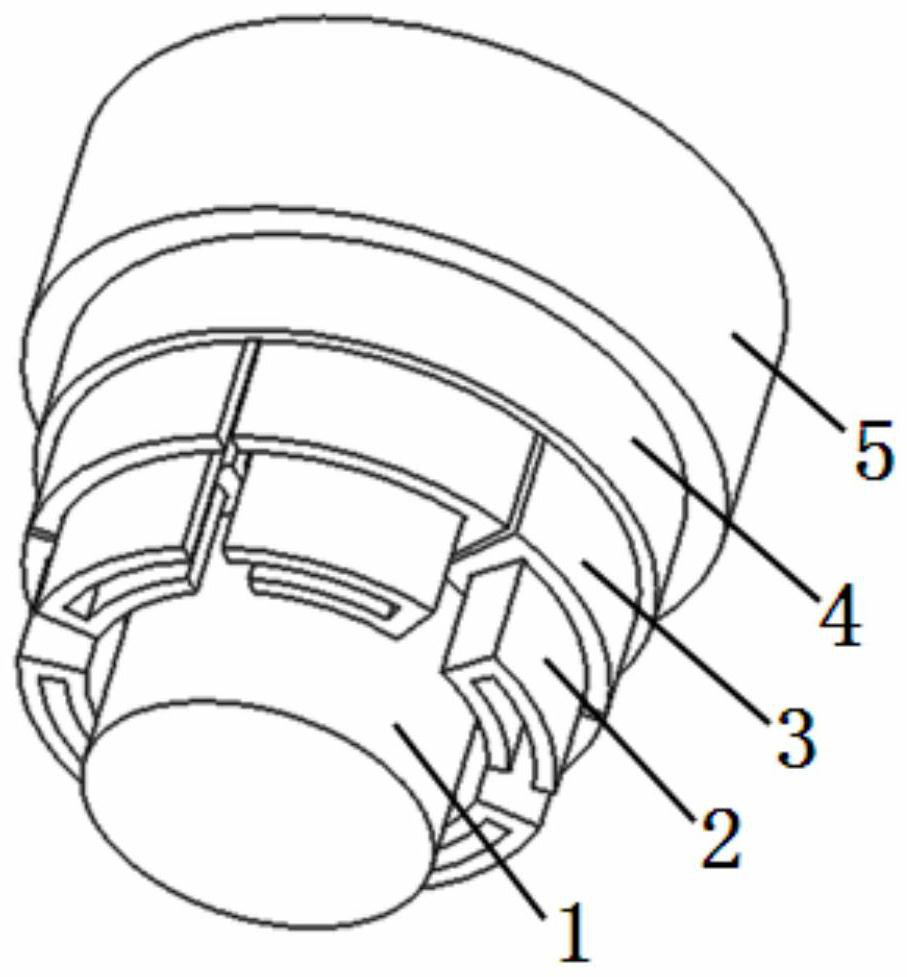
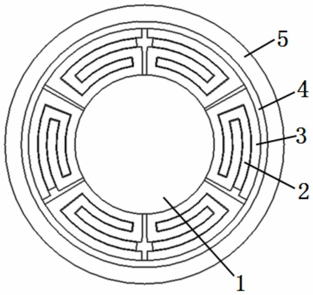
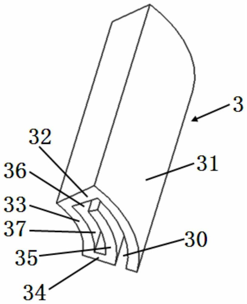
[0066]Please seeFigure 1 to Figure 8 , A power cable with a reinforcing part 1, six accommodating parts 3 distributed on the outer edge of the reinforcing part, a protective layer 4 located outside all the accommodating parts, and an outer protective layer 5 covering the protective layer, each The accommodating component has a power transmission component 2 inside; it is characterized in that the accommodating component 3 is sequentially connected by a third bending portion 31, a second connecting portion 32, a fourth bending portion 33, a third connecting portion 34, and a fifth bending portion. The second cavity 30 is formed between the third bending portion 31 and the fifth bending portion 35. The fifth bending portion is not connected to the third bending portion, and the fifth bending portion is not connected to the first bending portion. There is a fourth cavity 37 between the fourth curved portion 33 and the fifth curved portion 35, a third cavity 36 is provided between the s...

Embodiment 2

[0092]Please seePicture 9 And refer toFigure 1 to Figure 8 , A power cable, basically the same as the first embodiment, except that the open ends of the second cavity are distributed in the same direction;Picture 9 The middle is distributed clockwise or counterclockwise.

[0093]The above-mentioned power cable is characterized in that the lower surface of the first bending portion of the first bending portion in the second cavity is located above the lower surface of the third connecting portion; the lower surface of the first bending portion can also be connected to the third The lower surface of the part is in the same plane, which increases the area of ​​the first curved part, that is, the conductor area, that is, the conductive capacity.

Embodiment 3

[0095]Please seePicture 10 And refer toFigure 1 to Figure 9 , A power cable, basically the same as the first embodiment, the difference is: there are three accommodating parts 3 outside the reinforcing part 1, each accommodating part has a power transmission part 2 inside, and the three accommodating parts outside the inner ring The part is the same as that of Example 1.

[0096]Of course, there can also be multiple accommodating parts in the inner ring.

[0097]Of course, the distribution of the opening ends of the second cavity of the accommodating part of the inner ring can also be distributed in the same direction as in Example 2, or not in the same direction; similarly, the distribution of the second cavity of the accommodating part of the outer ring The distribution of the open ends may also be distributed in the same direction as in Embodiment 2, or may not be distributed in the same direction.

[0098]In this embodiment, the power transmission capacity is increased, and in addition, ...


PUM


Abstract

The invention belongs to the technical field of electric power and cables, and relates to a power cable, which is provided with a reinforcing component, an accommodating component, a protective layerand an outer protective layer, wherein a power transmission component is arranged in the accommodating component, the accommodating component is composed of a third bent part, a second connecting part, a fourth bent part, a third connecting part and a fifth bent part, a second cavity, a fourth cavity and a third cavity are formed in the accommodating component, the second cavity is communicated with the third cavity, the third cavity is communicated with the fourth cavity, the accommodating component is of an integrated structure, the power transmission component is composed of a first bent part, a first connecting part and a second bent part, a first cavity is formed among the first bent part, the first connecting part and the second bent part, the second bent part is arranged in the fourth cavity, the first connecting part is arranged in the third cavity, and the first bent part is arranged in the second cavity. The invention also discloses a communication optical cable, a photoelectric composite cable and an optical fiber ribbon. According to the invention, the main beneficial effects of simple structure, easy stripping, good heat dissipation, lighter weight, lower cost and moreflexible use are achieved.

Description

Technical field[0001]The invention belongs to the technical field of electric power, cable and communication, and particularly relates to a power cable, a photoelectric composite cable, a communication optical cable and an optical fiber ribbon.Background technique[0002]In the prior art, the cables are stranded with round insulated wires, and the optical cables are stranded with round loose tubes, etc., which cause large damage to conductors and optical fibers or optical fiber ribbons, complex cable forming equipment required; large product diameters and high costs; In addition, the stripping of the conductor and the optical fiber ribbon is troublesome, the efficiency is low, and the conductor heat dissipation effect is poor.[0003]CN201408278U discloses an optical fiber cable for highly flexible drag chains. Including: optical fiber, optical fiber sheath, fiber unit sheath, FRP (fiber reinforced plastic) reinforcement, non-woven fabric wrapping layer, inner sheath, reinforcement laye...

Claims


Application Information

Patent Timeline
IPC IPC(8): H01B9/00H01B7/02H01B7/38H01B7/42H01B11/22G02B6/44
CPCH01B9/006H01B9/005H01B7/02H01B11/22H01B7/38H01B7/42G02B6/443G02B6/4432G02B6/4403
Inventor 沈群华
Owner CHANGSHU BAILIAN PHOTOELECTRIC TECH CO LTD
Learn More