
Simulation optical eye function model

A functional model, optical technology, used in teaching models, educational appliances, instruments, etc.

Pending Publication Date: 2020-12-29
北京恒康敏科技有限公司
View PDF3 Cites 3 Cited by
  • Summary
  • Abstract
  • Description
  • Claims
  • Application Information

AI Technical Summary

Problems solved by technology

[0005] The technical problem to be solved by the present invention is to provide a simulated optical eye function model, which can be used to demonstrate the optical function of the human eye, simulate the biological characteristic changes of each optical structure of the eye, so as to understand the influence of the optical structure on light refraction and aberration, Computational methods used in optometry to calculate and correct refractive problems, visualize and visualize problems that are difficult to understand in optometry

Method used


Image

  • Simulation optical eye function model
  • Simulation optical eye function model
  • Simulation optical eye function model

Examples


Embodiment 1

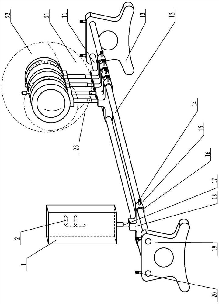
[0034] like figure 1 As shown, a kind of simulated optical eye function model of the present invention includes optical bench, light source assembly, cornea assembly, iris assembly, lens assembly and retina assembly, and described optical bench includes first seat board 19, second The seat plate 12, the first guide rail 11 and the second guide rail 13 respectively offer guide rail insertion holes on the first seat plate 19 and the second seat plate 12, and the two ends of the first guide rail 11 and the second guide rail 13 are inserted through the guide rail. The holes are installed in parallel between the first seat plate 19 and the second seat plate 12; the light source assembly, cornea assembly, iris assembly, lens assembly and retina assembly all include a base slider 18, on which the base slider 18 The first sliding hole 25 and the second sliding hole 16 are set, and the base slider 18 is installed on the first guide rail 11 and the second guide rail 13 through the first...

Embodiment 2

[0057] Such as figure 2 As shown, in this embodiment, the bionic eyeball shell is also included, and the bionic eyeball shell includes an upper spherical shell 22, a lower left spherical shell 21 and a lower right spherical shell 23, and the upper spherical shell 22, the lower left spherical shell 21 and the lower right spherical shell 23 can form a bionic eyeball by magnetically attracting or bonding or bolting into one; The lens assembly and retina assembly are wrapped. Draw or sculpt the images and structures of the muscles and blood vessels of the eyeball on the bionic eyeball shell.

[0058] The bionic eyeball shell designed in this example is 3D modeled on the basis of simulation, and the model is enlarged at 1:6 to keep the actual shape and anatomical structure of the eyeball as much as possible, such as the distribution of muscles and blood vessels of the eyeball, within the bionic eyeball shell Demonstrating the positions of cornea, iris, lens, and retina in sequen...

Embodiment 3

[0084] Such as Figure 9 As shown, in this embodiment, a diopter adjustment assembly is also included, and the refraction adjustment assembly is arranged between the light source assembly and the cornea assembly. Such as Figure 10 As shown, the refraction adjustment assembly includes a refraction adjustment frame 33, and the front side of the refraction adjustment frame 33 is provided with a diopter tab 32, and more than two diopter tabs can be fixed in the diopter tab 32. Refractive lens 34; the refraction adjustment frame 33 is installed on the base slider of the refraction adjustment assembly through a damping telescopic rod.

[0085] The refraction adjustment assembly described in this embodiment is a mature existing technology, which has been widely used in the special trial frame structure for glasses. It is "A Trial Frame That Can Measure and Adjust the Tilt Angle of Body and Legs", and the patent number is 201611139583.1, and the patent name is "Trying Mirror Frame"...


PUM


Abstract

The invention discloses a simulation optical eye function model, and belongs to the technical field of simulation eye models for teaching. The model comprises an optical bench base, a light source assembly, a cornea assembly, an iris assembly, a lens assembly and a retina assembly, the optical bench base comprises a first base plate, a second base plate, a first guide rail and a second guide rail,the first and second base plate are separately provided with guide rail insertion holes, and the two ends of the first guide rail and the second guide rail are arranged between the first seat plate and the second seat plate in parallel in a penetrating mode through the guide rail insertion holes; and base sliding blocks of the light source assembly, the cornea assembly, the iris assembly, the crystalline lens assembly and the retina assembly are installed on the first guide rail and the second guide rail through a first sliding hole and a second sliding hole and can slide along the rails. Themodel can be used for demonstrating the optical function of human eyes and simulating the biological characteristic change of optical structures of the eyes, so that the influence of the optical structures on light refraction and aberration is understood, a calculation method used for visual optics is used for calculating and correcting the refraction problem, and the problem which is difficult to understand by eye optics is visualized.

Description

technical field [0001] The technical field of the simulation eye model for teaching of the present invention, in particular relates to a simulation optical eye function model. Background technique [0002] The human eye is often the optical equivalent of a camera. The iris is compared to the shutter, the pupil is compared to the aperture, the crystal is compared to the lens, the retina is compared to the film, and both have lens systems to focus light. Although there are many similarities, the main difference between the two systems is the mechanism by which objects are focused. In a camera, the focal length of each lens is fixed, and changes in focus are caused by movement of the lens. However, in the human eye, it is through changing the curvature of the lens that the optical power of the lens is changed, thereby causing a change in focus. [0003] At present, the physical model of the eyeball is mainly to solve the anatomical structure of the eyeball and a simple model...

Claims


Application Information

Patent Timeline
IPC IPC(8): G09B23/32G09B23/22
CPCG09B23/32G09B23/22
Inventor 杨亚军马明朱简马峰王曌朱康马艺心马子木
Owner 北京恒康敏科技有限公司
Learn More