
Tunnel dimming structure with pollutant degradation function

A technology for structures and pollutants, applied in the field of tunnel operation safety, can solve the problems of lengthening tunnel length, high pollutant concentration, increasing the brightness of tunnel openings, etc., and achieve the effects of strengthening catalytic performance, optimizing catalytic efficiency, and increasing contact area

Active Publication Date: 2020-12-29
CHINA JILIANG UNIV
View PDF7 Cites 2 Cited by
  • Summary
  • Abstract
  • Description
  • Claims
  • Application Information

AI Technical Summary

Problems solved by technology

But its disadvantage is that the existing tunnel entrance light-reduction structures are basically a grid design, which increases the brightness of the tunnel entrance and also increases the power consumption inside the tunnel entrance to enhance lighting. The existing full-coverage and half-coverage tunnel entrance shading sheds are equivalent to lengthening the length of the tunnel, making it more difficult for the pollutants such as automobile exhaust accumulated at the tunnel entrance to be discharged, which further aggravates the problem of pollutant accumulation at the tunnel entrance
Considering that ① the light intensity at the tunnel entrance changes drastically, the use of auxiliary lighting consumes a large amount of power resources, while the use of ordinary light-reducing structures does not take into account the energy consumption of the internal lighting of the tunnel entrance; ② the vicinity of the tunnel entrance is a pollutant gathering area such as automobile exhaust , the high concentration of pollutants threatens the traffic safety at the tunnel entrance and the health of residents near the tunnel entrance. The general light reduction structures at the tunnel entrance do not consider the degradation of pollutants at the tunnel entrance. Therefore, it is urgent to solve the above-mentioned problems of energy saving and emission reduction at the tunnel entrance.

Method used


Image

  • Tunnel dimming structure with pollutant degradation function
  • Tunnel dimming structure with pollutant degradation function
  • Tunnel dimming structure with pollutant degradation function

Examples


Embodiment Construction

[0021] The present invention will be further described in detail below in conjunction with the accompanying drawings and specific embodiments.

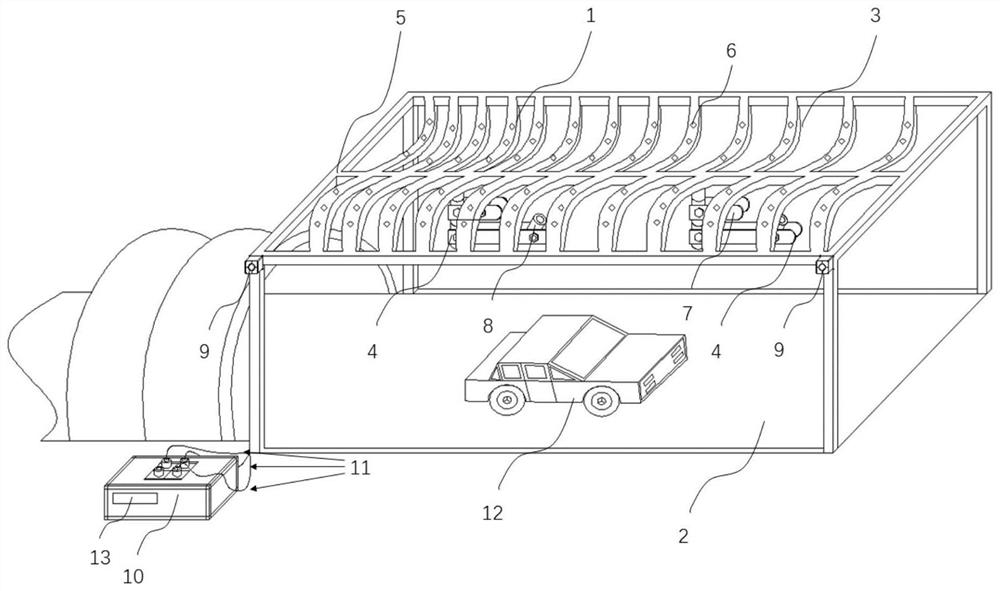
[0022] According to a large number of experimental studies, the impact of drastic changes in the light environment near the tunnel entrance on drivers is mainly in the range from the parking sight distance in front of the tunnel entrance to the boundary between the enhanced lighting section and the transitional lighting section inside the tunnel. In this area of ​​influence, it is generally necessary to reduce the drastic changes of light through facilities such as light-reducing grilles. Since the vehicle has a certain driving speed when passing through the tunnel opening, the light-reducing structures are too short to meet the time requirements for human eyes to adapt to light, and the light-reducing structures Light structures that are too long will increase the project cost. The length of the light reduction structure can be calcu...


PUM

PropertyMeasurementUnit
lengthaaaaaaaaaa
widthaaaaaaaaaa
transmittivityaaaaaaaaaa

Abstract

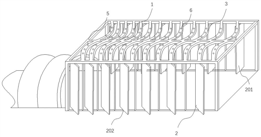
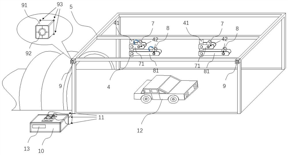
The invention discloses a tunnel dimming structure with a pollutant degradation function, belongs to the field of transportation, and particularly relates to a tunnel operation safety facility. The structure comprises a light reduction structure arranged at an entrance and exit of a tunnel, a pollutant degradation coating and an ultraviolet lighting system assisting in enhancing pollutant degradation, the light reduction structure is an S-shaped grating light reduction structure, and the pollutant degradation coating is made of a TiO2 photocatalytic material. The coating is coated on the sidewall surface of the light reduction structure in two modes according to the pollutant distribution rule of the tunnel portal, and the ultraviolet lighting system comprises an ultraviolet illuminationlamp combination and an ultraviolet illumination dynamic control system. According to the structure, uniform transition of light at the tunnel portal is effectively achieved, the contact area betweenthe device and pollutants is increased, natural light and an ultraviolet lamp are used for assisting in irradiating on the light reduction structure coated with a TiO2 photocatalytic material, the photocatalytic material is further made to effectively degrade the pollutants, the air environment of the tunnel portal is improved, and tunnel safety and environmental friendliness are facilitated.

Description

technical field [0001] The invention relates to a tunnel light reduction structure with the function of pollutant degradation, in particular to the field of tunnel operation safety. Background technique [0002] With the development of the economy, a large number of road traffic facilities have been constructed. In order to alleviate the problem of excessive road traffic load, tunnel construction has become an important measure to save land resources and alleviate road traffic congestion. In the operation of urban and highway tunnels, passing vehicles enter the dark environment of the tunnel from the brighter environment outside, or enter the bright environment from the dark environment of the tunnel, the drastic changes in light and dark light will cause visual fatigue and even temporary blindness of the driver, etc. It is not conducive to driving traffic safety. Therefore, many tunnel entrances are specially equipped with enhanced lighting devices to enhance the brightnes...

Claims


Application Information

Patent Timeline
Patent Type & Authority Applications(China)
IPC IPC(8): F21S9/03F21V19/00F21V23/00F21V23/04F21V33/00E21D9/14B01D53/94B01D53/38F21W131/101
CPCF21S9/032F21V19/00F21V23/02F21V23/0464F21V33/00E21D9/14B01D53/94F21W2131/101B01D2255/20707B01D2255/802B01D2259/804Y02B20/72
Inventor 朱凯张琼华陈亚苗王强李海航
Owner CHINA JILIANG UNIV
Learn More