Full-automatic ink printing die-cutting machine
A die-cutting machine, fully automatic technology, applied in printing presses, rotary presses, printing and other directions, can solve the problems of unfavorable corrugated cardboard production and manufacturing ink printing processing quality, corrugated cardboard corrugated damage is large, increase the inner paper and face paper, etc. problems, to achieve the effect of benefiting manufacturing and ink printing processing quality, ensuring the continuity of deformation, and improving the scope of application
- Summary
- Abstract
- Description
- Claims
- Application Information
AI Technical Summary
Problems solved by technology
Method used
Image
Examples
Embodiment 1
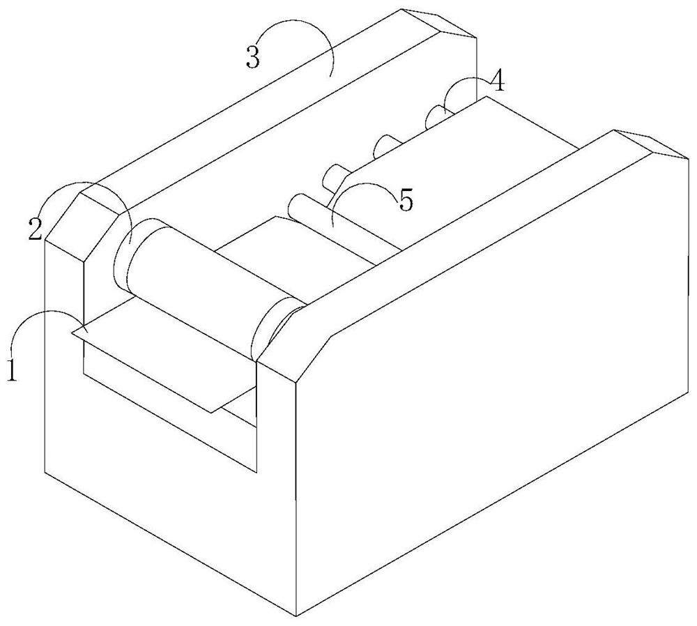
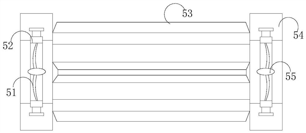
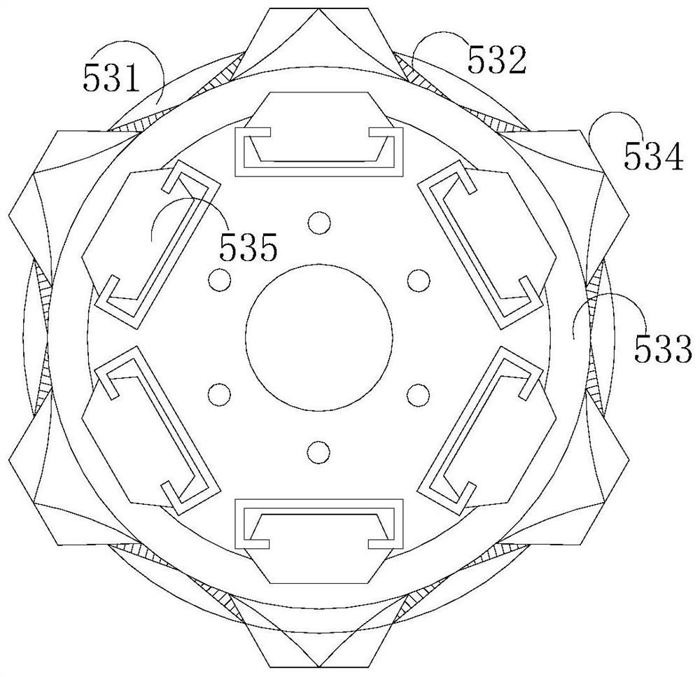
[0031] Such as Figure 1-Figure 4 As shown, the present invention provides a kind of automatic ink printing die-cutting machine, and its structure comprises conveying plate 1, integration roller 2, frame 3, conveying roller 4, die-cutting device 5, described conveying roller 4 and die-cutting device 5 The transmission plate 1 is gap-fitted between them, and one end of the transmission plate 1 is interspersed and arranged under the conveying roller 4 through the frame 3. The die-cutting device 5 includes a guide shuttle 51, a top support frame 52, a crimping roller 53, a horizontal Cavity 54, driver 55, the two ends of the crimping roller 53 are fixedly connected with a lying cavity 54, a top frame 52 is installed in the lying cavity 54, and a driver 55 is welded in the middle of the top frame 52, so The driving machine 55 is electrically connected to the crimping roller 53 through the guide shuttle 51. The crimping roller 53 includes an apron 531, a slideway 532, a transition ...
Embodiment 2
[0033] Such as Figure 5-Figure 7As shown, on the basis of Embodiment 1, the present invention combines the mutual cooperation of the following structural components. The adjustment device 534 includes a top piece 341, a cushion sleeve 342, a positioning piece 343, a locking ball 344, a bending hook 345, The extension structure 346, the tip piece 341 is a triangular structure, the two sides of the tip are fixedly connected with the extension structure 346, the other end of the extension structure 346 is welded to the bending hook 345, and the bending hook 345 is connected by bolts The positioning part 343 is connected with the positioning part 343, the positioning part 343 is installed on the outer circumference of the locking ball 344, and the locking ball 344 is movably engaged in the inside of the cushion sleeve 342, and the bending hook 345 is a soft rubber support , one side of which is a bayonet-shaped structure, and the extension structure 346 includes a guide connectin...
PUM
 Abstract
Description
Claims
Application Information
 - R&D
- Intellectual Property
- Life Sciences
- Materials
- Tech Scout
- Unparalleled Data Quality
- Higher Quality Content
- 60% Fewer Hallucinations
Browse by: Latest US Patents, China's latest patents, Technical Efficacy Thesaurus, Application Domain, Technology Topic, Popular Technical Reports.
© 2025 PatSnap. All rights reserved.Legal|Privacy policy|Modern Slavery Act Transparency Statement|Sitemap|About US| Contact US: help@patsnap.com


