
Anti-condensation device and method for box-type equipment

A technology for anti-condensation and equipment, which is applied to the panel/switching station circuit device, substation/distribution device shell, substation/switching device cooling/ventilation, etc., which can solve the aging failure of moisture absorbent, high cost, and complex equipment configuration and other problems, to achieve the effects of shortening working hours, improving dehumidification efficiency, and excellent anti-condensation

Inactive Publication Date: 2020-12-25
STATE GRID JIANGXI ELECTRIC POWER CO LTD RES INST +1
View PDF5 Cites 3 Cited by
  • Summary
  • Abstract
  • Description
  • Claims
  • Application Information

AI Technical Summary

Problems solved by technology

[0005] The dehumidifier dehumidification method absorbs moisture in the air through solid or liquid hygroscopic agents to reduce the air humidity to achieve the purpose of anti-condensation, but there is a problem of aging and failure of the hygroscopic agent, which requires frequent replacement, which increases the workload and cannot accurately control the air humidity.
[0006] The condensation dehumidification method uses refrigeration equipment to cool the air temperature below the dew point temperature, so that the water vapor in the air is liquefied into water droplets, which are discharged through the water pipe, thereby reducing the air humidity in the cabinet to achieve the purpose of anti-condensation, but this method has equipment Constitute complex, costly and energy-intensive problems
[0007] The heating dehumidification method uses air heaters and other equipment to heat the air in the cabinet, the air temperature in the cabinet rises, the moisture changes from liquid to gaseous, and is discharged through ventilation, thereby reducing the air humidity in the cabinet and achieving the effect of anti-condensation. Compared with the above two methods, this method is easy to maintain, simple in equipment and low in energy consumption. It is widely used in practice, but the anti-condensation effect cannot meet the requirements.

Method used


Image

  • Anti-condensation device and method for box-type equipment
  • Anti-condensation device and method for box-type equipment
  • Anti-condensation device and method for box-type equipment

Examples


Embodiment Construction

[0030] The following will clearly and completely describe the technical solutions in the embodiments of the present invention with reference to the accompanying drawings in the embodiments of the present invention. Obviously, the described embodiments are only some, not all, embodiments of the present invention. The following description of at least one exemplary embodiment is merely illustrative in nature and in no way taken as limiting the invention, its application or uses. Based on the embodiments of the present invention, all other embodiments obtained by persons of ordinary skill in the art without creative efforts fall within the protection scope of the present invention.

[0031] It should be noted that the terminology used here is only for describing specific implementations, and is not intended to limit the exemplary implementations according to the present application. As used herein, unless the context clearly dictates otherwise, the singular is intended to include...


PUM

PropertyMeasurementUnit
angleaaaaaaaaaa

Abstract

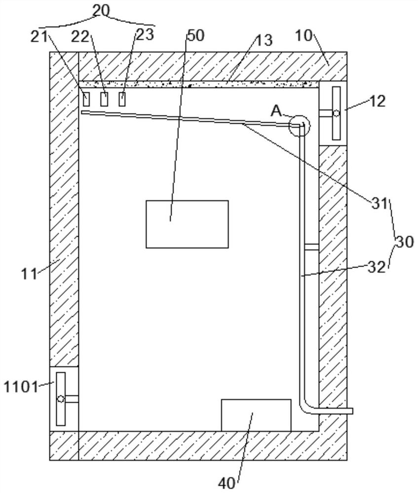
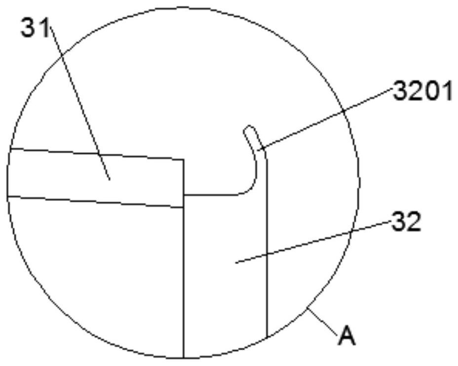
The invention discloses an anti-condensation device for box-type equipment, and the device comprises: a cabinet body, wherein the inner wall of the upper part of the cabinet body is provided with a super-hydrophobic coating; a drainage assembly which is detachably installed in the cabinet body, wherein the drainage assembly is located under the super-hydrophobic coating, and the length of the upper portion of the drainage assembly is smaller than the width of the cabinet body so that the interior of the cabinet body can be communicated, wherein the upper portion of the drainage assembly is obliquely arranged downwards in the direction from one side of the cabinet body to the other opposite side of the cabinet body, and the lower portion of the drainage assembly partially extends out of thecabinet body. By arranging the super-hydrophobic coating and the drainage assembly, a part of humidity in the cabinet body can be reduced, so that the working time of later dehumidification is effectively shortened, and the effects of reducing energy consumption and remarkably improving the dehumidification efficiency are achieved; through combination of super-hydrophobic coating dehumidificationand heating ventilation dehumidification, a multi-stage dehumidification effect is achieved, so that the humidity in the box-type equipment cabinet can be effectively reduced, and an excellent anti-condensation effect is achieved.

Description

technical field [0001] The invention belongs to the technical field of anti-condensation for electric equipment, and in particular relates to an anti-condensation device and method for box-type equipment. Background technique [0002] Modern power systems have higher and higher requirements for power supply safety and reliability. Box-type electrical equipment such as ring network cabinets, switch cabinets, box-type substations, and cable branch boxes are the core components of the power system, and their safe and stable operation is the key to power supply. The basis for safe and reliable power supply of the system. However, these box-type equipment generally have the problem of condensation caused by the decrease of the external temperature and the high humidity inside the cabinet, and there is also the possibility of condensation adhesion in the structure of each component inside the cabinet of the box-type equipment. [0003] Condensation phenomenon refers to the conden...

Claims


Application Information

Patent Timeline
Patent Type & Authority Applications(China)
IPC IPC(8): H02B1/28H02B1/30H02B1/46H02B1/56H02B1/24G05D27/00G05D27/02
CPCH02B1/28H02B1/30H02B1/306H02B1/46H02B1/24H02B1/565G05D27/00G05D27/02
Inventor 王华云邓志祥蔡木良黄佩戚沁雅郝钰
Owner STATE GRID JIANGXI ELECTRIC POWER CO LTD RES INST
Learn More