An over-pcb board connector capable of observing and verifying the annular gap on the back

A PCB board and ring gap technology, which is applied in the direction of connection, two-part connection device, and parts of the connection device, can solve problems such as image acquisition obstacles, safety hazards, and unstable electrical connections, and achieve improved connection stability and fast Effect of machine inspection and reduction of metal material consumption

Active Publication Date: 2022-08-02
SHANGHAI LAIMU ELECTRONICS
View PDF0 Cites 0 Cited by
  • Summary
  • Abstract
  • Description
  • Claims
  • Application Information

AI Technical Summary

Problems solved by technology

[0003] However, when the connector is in use, because the insertion tongue of the male terminal and the female terminal insertion groove of the female terminal are single-sided and single-contact, the contact area is small, the contact impedance value is relatively large, the heat generation is large, and the heat dissipation effect is poor. , which poses a safety hazard to the
[0004] In the prior art, the male end and the female end of the electrical connector are either connected by wires, which is very troublesome and has the defect of weak connection, or a male-female butt joint connection is used, and the existing electrical connection is carefully analyzed. According to the terminal structure of the device, it is not difficult to find that most of the male terminals and female terminals directly form a single raised shrapnel contact at the position where they contact each other. The shrapnel has weak elasticity, poor contact contact tightness, unstable electrical connection, and poor reliability. There is a need for improvement
[0005] At present, the rise of computer vision algorithms provides a new idea for the verification of connector connection stability. The connection area can be visually identified through the algorithm, and the analysis of the tightness of the contact points can be realized through the analysis of the boundary contour. However, the current connector The contact positions of the male terminal and the female terminal are both inside the connection structure, which creates obstacles to the collection of pictures

Method used


Image

  • An over-pcb board connector capable of observing and verifying the annular gap on the back
  • An over-pcb board connector capable of observing and verifying the annular gap on the back
  • An over-pcb board connector capable of observing and verifying the annular gap on the back

Examples


Embodiment

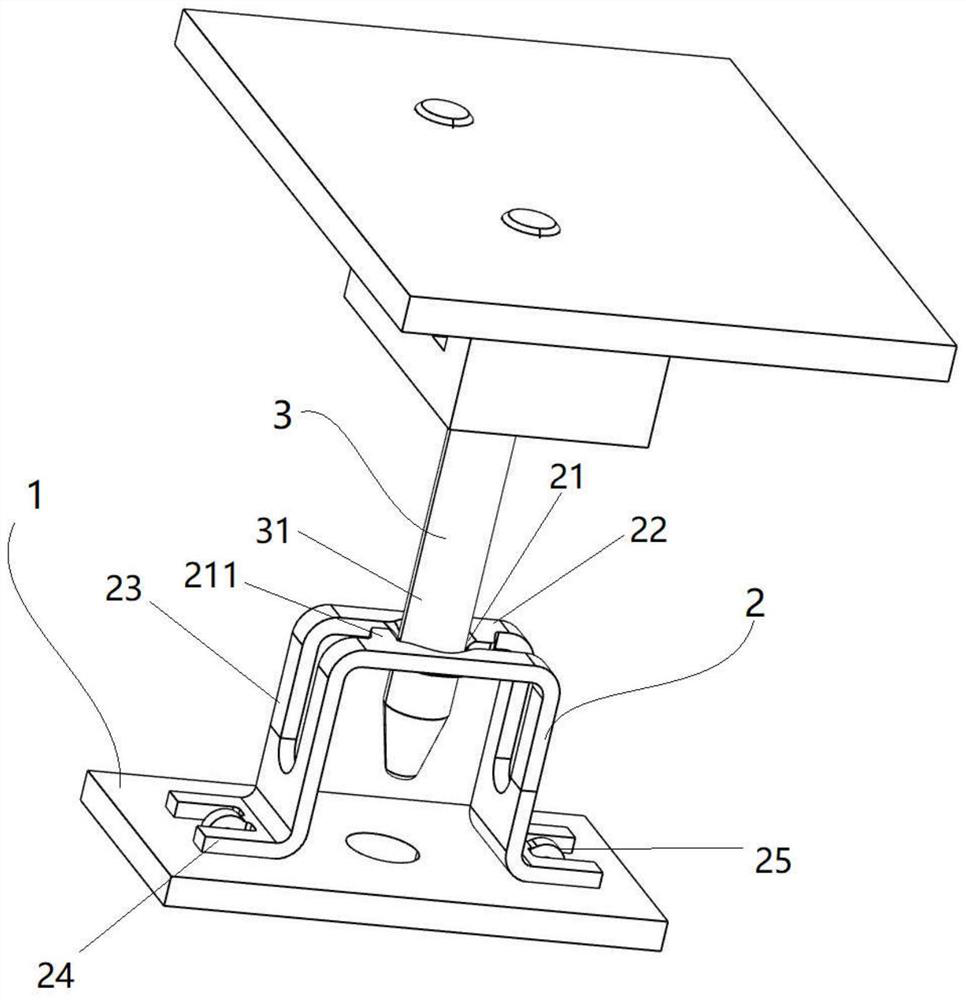
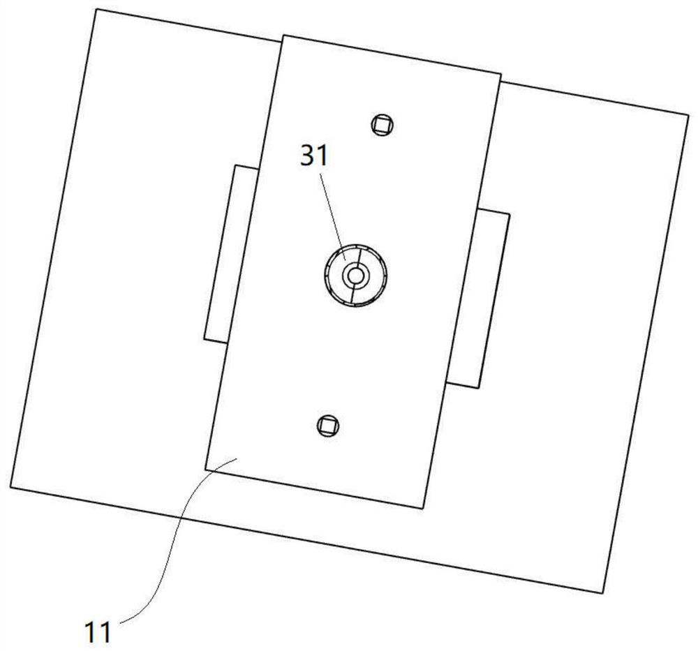
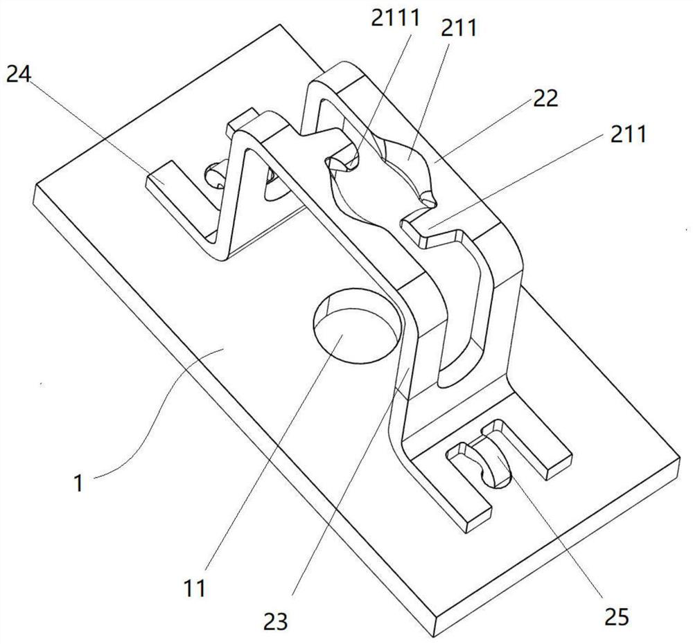
[0032] The PCB board-type connector capable of observing and verifying the annular gap on the back of the present invention includes a PCB board 1 , a positive U-shaped female terminal 2 and a male terminal 3 , see figure 1 and figure 2 . The PCB board 1 is provided with insertion holes 11; both ends of the positive U-shaped female terminal 2 are fixedly connected to the PCB board 1, and the positive U-shaped female terminal 2 is provided with a connecting hole 21; the male terminal 3 includes a A cylindrical connecting pin 31 at the tip, the connecting pin 31 first passes through the connecting hole 21 and then passes through the insertion hole 11 , the inner diameter of the insertion hole 11 is larger than the outer diameter of the male terminal 3 , and only the insertion hole 11 is required in the specific implementation. The inner diameter is slightly larger than the outer diameter of the male terminal 3. The outer wall surface of the connecting pin 31 and the connecting...


PUM


Abstract

The invention relates to a PCB board connector capable of observing and verifying the annular gap on the back, comprising a PCB board, a positive U-shaped female terminal and a male terminal, wherein the PCB board is provided with a plug-in hole; the two ends of the positive U-shaped female terminal are fixed Connected to the PCB board, the positive U-shaped female terminal is provided with a connection hole; the male terminal includes a columnar connection pin with a tip, the connection pin first passes through the connection hole and then passes through the insertion hole, the The outer wall surface of the connecting pin and the connecting hole form a 4-segment contact structure, and at the same time, the frontal observation verification of the 4-segment contact structure can be realized from the visual annular gap formed by the back of the plug hole 11 and the male terminal 3 . Compared with the prior art, the present invention realizes a 4-section contact structure through the connection structure formed by the positive U-shaped female terminal and the PCB board, and at the same time, a clear photo of the contact area can be obtained through the image acquisition device, so as to realize the industrial robot. Quick machine inspection.

Description

technical field [0001] The invention relates to a connector, in particular to an over-PCB board connector capable of observing and verifying the back annular gap. Background technique [0002] The connector terminal includes a male terminal and a female terminal. The male terminal has a plug-in tongue and a male-end connecting part, and the male-end connecting part is connected with the plug-in tongue. The female terminal has a female end base and a female end connecting portion, and the female end connecting portion and the female end base are connected. When in use, the insertion tongue of the male terminal is inserted into the female terminal insertion groove of the female terminal. [0003] However, when the connector is in use, because the plug tongue of the male terminal and the female terminal socket of the female terminal are in single-sided single contact, the contact area is small, the contact resistance value is relatively large, the heat generation is large, and...

Claims


Application Information

Patent Timeline
Patent Type & Authority Patents(China)
IPC IPC(8): H01R13/11H01R13/04H01R12/71H01R24/00
CPCH01R13/111H01R13/04H01R12/718H01R24/00
Inventor 谭海明俞良浩程钊朱新爱
Owner SHANGHAI LAIMU ELECTRONICS
Why Eureka
Try Eureka