
Sensing device based on optical fiber surface enhanced Raman probe and working method

A technology of surface-enhanced Raman and sensing devices, applied in the field of spectral detection, can solve problems affecting the quality of Raman spectral signals, overlapping optical fibers, etc., and achieve the effects of reversible optical path, low insertion loss, and reduced harm

Pending Publication Date: 2020-12-25
LASER RES INST OF SHANDONG ACAD OF SCI
View PDF7 Cites 0 Cited by
  • Summary
  • Abstract
  • Description
  • Claims
  • Application Information

AI Technical Summary

Problems solved by technology

However, when surface-enhanced Raman scattering fiber probes are used for inspection, the fiber itself will also generate Raman scattered light (except for hollow fibers), which will cause the Raman noise of the fiber to overlap with the Raman signal band of the sample, which will seriously affect The quality of the acquired Raman spectroscopic signal

Method used


Image

  • Sensing device based on optical fiber surface enhanced Raman probe and working method
  • Sensing device based on optical fiber surface enhanced Raman probe and working method
  • Sensing device based on optical fiber surface enhanced Raman probe and working method

Examples


Embodiment 1

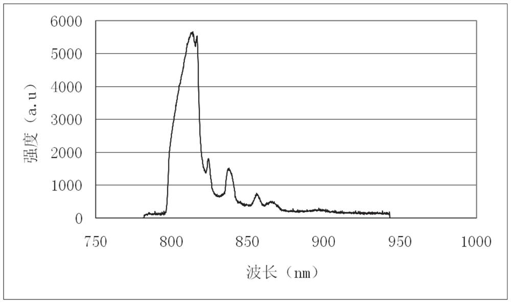
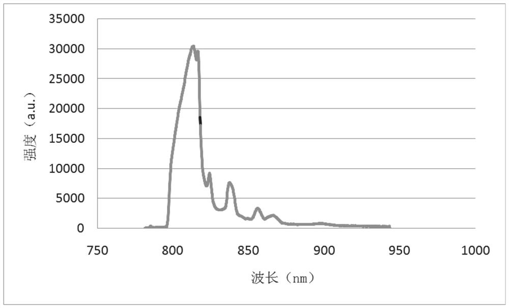
[0041] In a typical implementation of the present disclosure, such as Figure 1-Figure 5 As shown, a sensing device based on a fiber-optic surface-enhanced Raman probe is proposed.

[0042] It mainly consists of single-frequency laser, Raman probe, collimator lens, first plane mirror, second plane mirror, first fiber collimator, second fiber collimator, reference fiber, fiber probe and Raman spectrometer;

[0043] Among them, the Raman probe, collimating lens and fiber collimator arranged in sequence can form an optical path, the Raman probe is connected with the laser and the spectrometer, and the first fiber collimator connected with the first optical fiber and the collimating lens are arranged between the first fiber collimator and the collimating lens. Detachable plane mirror group, the plane mirror group can obtain the laser light emitted by the collimating lens and reflect it to the second fiber collimator connected with the second optical fiber;

[0044] Wherein, the p...

Embodiment 2

[0067] In another typical implementation of the present disclosure, such as Figure 1-Figure 5 As shown, a working method of the sensing device based on the optical fiber surface-enhanced Raman probe in Example 1 is given.

[0068] Include the following steps:

[0069] When the first plane mirror 4 was in the separated state, the excitation light emitted by the single-frequency laser 1 was incident on the excitation fiber of the Raman probe 2, then output by the oil-immersion objective lens of the Raman probe, and then incident on the first plane mirror 4 through the collimating lens 3. On the fiber collimator 6;

[0070] Finally input to the reference optical fiber 8, the Raman scattered light produced by the reference optical fiber returns to the Raman probe through the first optical fiber collimator 6 and the collimating lens, and then the Raman probe collects the optical fiber and transmits it to the Raman spectrometer 10, and is controlled by the computer 11 The softwar...


PUM

PropertyMeasurementUnit
lengthaaaaaaaaaa

Abstract

The invention provides a sensing device based on an optical fiber surface enhanced Raman probe and a working method, and relates to the field of spectrum detection. The device comprises a Raman probe,a collimating lens and optical fiber collimators which are arranged in sequence, wherein the Raman probe is connected with a laser and a spectrograph; a detachable plane mirror group is arranged between the first optical fiber collimator connected with a first optical fiber and the collimating lens; the plane mirror group can acquire laser emitted by the collimating lens and reflect the laser tothe second optical fiber collimator connected with a second optical fiber; two measurement channels with reversible optical paths and low optical loss are acquired through a shifting optical element;a Raman scattering spectrum of the optical fiber can be measured at any time; removal of Raman scattering background light of the optical fiber is realized; and high-sensitivity and portable Raman spectrum detection of trace toxic and harmful substances is realized by utilizing the optical fiber surface enhanced Raman probe.

Description

technical field [0001] The present disclosure relates to the field of spectrum detection, in particular to a sensing device and working method based on an optical fiber surface enhanced Raman probe. Background technique [0002] The statements in this section merely provide background information related to the present disclosure and may not necessarily constitute prior art. [0003] Substance identification and detection technology has important applications in the fields of food safety, environmental protection and life sciences, and its importance to the quality of life of people is self-evident. Surface-enhanced Raman scattering detection can provide spectral information about the fine structure of molecules, and is a highly sensitive, label-free detection method for molecular recognition. In recent years, with the help of the miniaturization and miniaturization of Raman spectrometers, surface-enhanced Raman spectroscopy has gradually developed from laboratory technolog...

Claims


Application Information

Patent Timeline
Patent Type & Authority Applications(China)
IPC IPC(8): G01N21/65G01N21/01G02B17/06
CPCG01N21/658G01N21/01G02B17/06G01N2021/0112
Inventor 王金玉谢洪晶刘媛李振赵林侯墨语王兆伟董果风王纪强刘统玉吕蕾
Owner LASER RES INST OF SHANDONG ACAD OF SCI
Learn More