Production process of high-temperature-resistant porous isolating membrane

A production process and isolation film technology, applied in the field of high temperature resistant perforated isolation film production process, can solve problems such as low work efficiency, reduced service life of the winding roller, and need to stop for replacement.

Inactive Publication Date: 2020-12-25
浙江班萘特复合材料股份有限公司
View PDF0 Cites 0 Cited by
  • Summary
  • Abstract
  • Description
  • Claims
  • Application Information

AI Technical Summary

Problems solved by technology

[0005] The purpose of the present invention is to address the deficiencies of the prior art. By setting the switching mechanism to cooperate with the pressing mechanism, when the switching mechanism replaces the old and new winding rollers, the pressing mechanism is used to compress the porous isolation film under the traction. On the one hand, the tightening state is maintained between the pressing mechanism and the old winding roller, which is beneficial to the cutting component to cut the porous isolation film; on the other hand, the porous isolation film on the other end of the pressing mechanism The bulge occurs in the middle, which is beneficial to the effective superimposition of the raised part of the porous separator and the fastening groove of the new winding roller, so as to cooperate with the usual clamping of the raised part of the porous separator by the compensation component to realize the active winding of the porous separator work, thus solving the technical problem that it is necessary to stop the machine to replace the winding roller every time the winding work is completed, the work efficiency is low, and the long-term disassembly of the winding roller will reduce the service life of the winding roller

Method used


Image

  • Production process of high-temperature-resistant porous isolating membrane
  • Production process of high-temperature-resistant porous isolating membrane
  • Production process of high-temperature-resistant porous isolating membrane

Examples


Embodiment 1

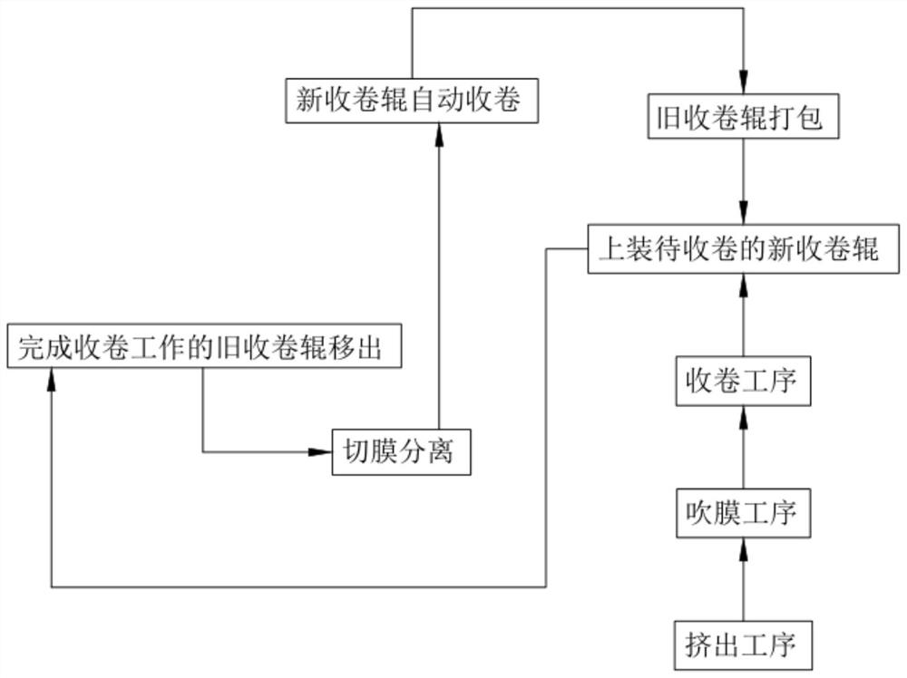
[0105] Such as figure 1 Shown, described a kind of production technology of high temperature resistant porous isolation film, comprises the following steps:

[0106] Step 1, the extrusion process, the extruder extrudes the high-temperature-resistant porous isolation film, and the high-temperature-resistant porous isolation film extruded in the extrusion process includes a three-layer structure arranged from top to bottom and the structure of each layer is the same, Any one layer contains antioxidant content ≤ 1%, synthetic agent content ≤ 1%, HDPE content ≥ 95% and high-territorial content ≥ 3%;

[0107] Step 2, film blowing process. The film blowing process is set at the output end of the extrusion process. The film blowing machine blows the high-temperature-resistant porous isolation film into a cylindrical shape, and flattens it for output after cooling;

[0108] Step 3, a winding process, the winding process is set at the output end of the film blowing process;

[0109] ...

Embodiment 2

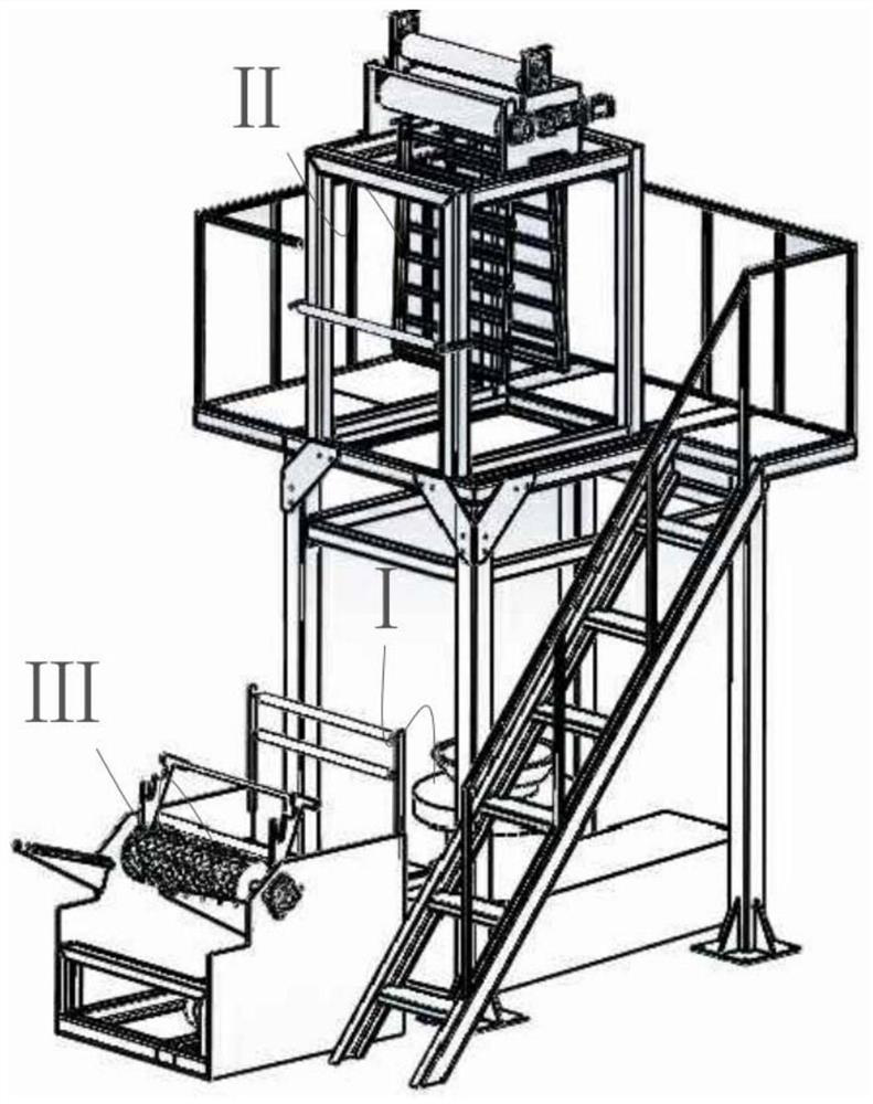
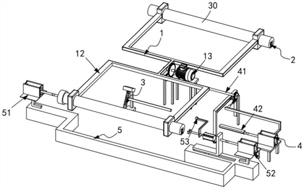
[0136] Such as Figure 4 , figure 2 and image 3 As shown, a high-temperature-resistant porous isolation film production system includes an extruder I, a film blowing machine II arranged on one side of the extruder, and a winder arranged on one side of the extruder I Ⅲ, the winder Ⅲ includes:

[0137] Switching mechanism 1, the switching mechanism 1 includes a translation assembly 12 and a first drive assembly 13 for driving the translation assembly 12 to rotate, one end of the translation assembly 12 is a winding station 10 and the other One end is the transmission station 20, the winding roller 30 is rotatably arranged on the translational assembly 12 and the compensating assembly 2 is arranged in it, and the lower end of the winding roller 30 is provided with a fastening groove 2a;

[0138] A pressing mechanism 3, the pressing mechanism 3 is located above the winding station 10;

[0139] The cutter mechanism 4, which is located between the winding station 10 and the tr...

Embodiment 3

[0182] Such as Figure 15 , Figure 16 , Figure 18 and Figure 21 As shown, the parts that are the same as or corresponding to those in the second embodiment are marked with the corresponding reference numerals in the second embodiment. For the sake of simplicity, only the differences from the second embodiment will be described below. The difference between this embodiment three and embodiment two is:

[0183] further, such as Figure 16 to Figure 15 As shown, the second drive assembly 52 includes a second flat-push cylinder 521 installed on the frame e520 with its telescopic end horizontally arranged, fixedly connected with the telescopic end of the second flat-push cylinder 521 and slidingly arranged at the lower end The motor frame 522 in the limit slot of the frame e520, the second drive motor 523 installed on the motor frame 522 and the plug block 524 arranged at the output end of the second drive motor 523, the plug block 524 is set There are chamfers and the cham...


PUM

PropertyMeasurementUnit
Widthaaaaaaaaaa
Lengthaaaaaaaaaa
Apertureaaaaaaaaaa

Abstract

The invention relates to a production process of a high-temperature-resistant porous isolating membrane,. The production process comprises the following steps: 1. an extrusion process: extruding a high-temperature-resistant porous isolating membrane by an extruder, wherein the high-temperature-resistant porous isolating membrane extruded in the extrusion process comprises three layers of structures that are arranged from top to bottom and have the same structures, the content of an antioxidant in any layer is less than or equal to 1%, the content of a lubricant is less than or equal to 1%, thecontent of a forming agent is less than or equal to 1%, the content of HDPE is greater than or equal to 95% and the content of kaolin is greater than or equal to 3%; 2, a membrane blowing process; 3,a rolling process, wherein the rolling process comprises the following steps: a) mounting a new wind-up roll to be rolled; b) moving out an old wind-up roll which completes the wind-up work; c) membrane cutting and separation; d) carrying out automatically rolling by the new wind-up roll; and e) manually replacing the wind-up roll, and rotating the wind-up roll to a transmission station. The production process solves the technical problems that the working efficiency is low after the wind-up work is completed each time as a machine is needed be stopped for replacing the wind-up roll, and theservice life of the wind-up roll will be shortened due to long-term disassembly of the wind-up roll.

Description

technical field [0001] The invention relates to the technical field of porous isolation membranes, in particular to a production process for high-temperature resistant porous isolation membranes. Background technique [0002] The air-permeable isolation film has air permeability, high temperature resistance and isolation, and is mainly used for vacuum infusion molding of wind power, yachts, aircraft seats, etc. During the production and processing of existing films, the film reel is often fixedly connected with the take-up shaft Just install the winding operation. After a winding operation is completed, the film reel needs to be disassembled from the rotating frame and replaced with a new film reel for rewinding. However, due to the complicated connection structure between the film reel and the frame, the It is very troublesome to disassemble and replace the film roll, which affects the processing efficiency. Therefore, we design a winding mechanism for film processing. [...

Claims


Application Information

Patent Timeline
IPC IPC(8): B29C48/10B29C48/00B29C48/28B29L7/00
CPCB29L2007/00B29C48/0017B29C48/0022B29C48/10B29C48/28
Inventor 金庭峰
Owner 浙江班萘特复合材料股份有限公司
Why Eureka
Try Eureka