Multifunctional non-setting adhesive die-cutting machine for label production

A multi-functional, labeling technology, applied in metal processing, etc., can solve the problems of high defective rate of finished labels, increase of enterprise cost, shortage of skilled workers, etc., to avoid mechanical damage, increase friction, and ensure work stability.

Inactive Publication Date: 2020-12-25
芜湖韩大防伪科技有限公司
View PDF0 Cites 0 Cited by
  • Summary
  • Abstract
  • Description
  • Claims
  • Application Information

AI Technical Summary

Problems solved by technology

At present, the die-cutting devices used by many small businesses are manual die-cutting machines, which need to be driven by the workers by stepping on the die-cutting machine to cut the required labels; and the cutting force also needs to be controlled manually. In order to prevent the release paper and the label from being die-cut and pass through together, the waste cannot be discharged. Therefore, the workers who perform this operation need to be skilled workers. Now skilled workers are in short supply and the labor cost is high, which increases the cost of the enterprise, and the finished label made by the manual die-cutting machine High defect rate, low work efficiency, time-consuming and labor-intensive

Method used


Image

  • Multifunctional non-setting adhesive die-cutting machine for label production
  • Multifunctional non-setting adhesive die-cutting machine for label production
  • Multifunctional non-setting adhesive die-cutting machine for label production

Examples


Embodiment 1

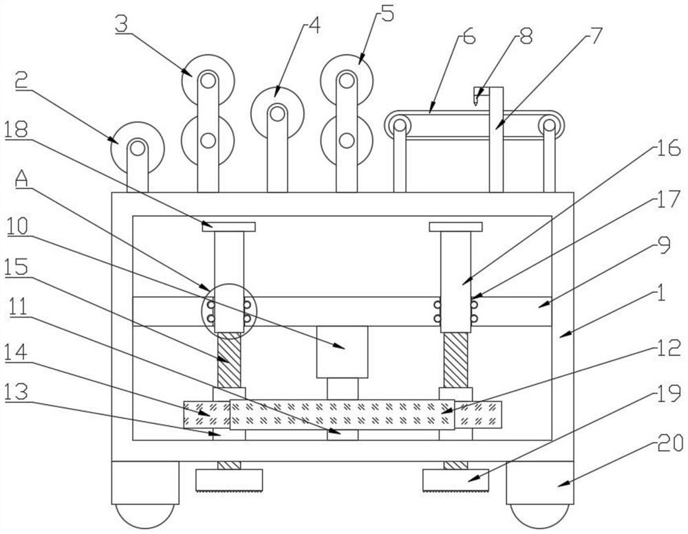
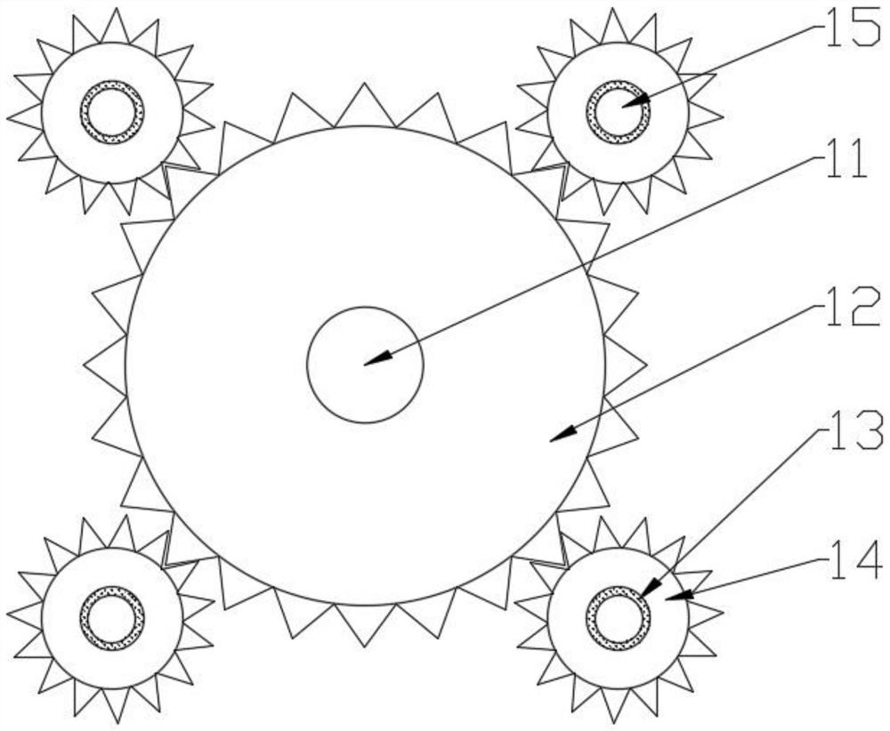
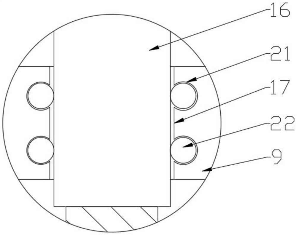
[0032] see Figure 1-3, a self-adhesive die-cutting machine for multifunctional label production, including a workbench 1, a conveyor belt 6 is arranged on the upper side of the workbench 1 to the right, the conveyor belt 6 is fixed on the upper surface of the workbench 1 through a bracket, and the upper surface of the workbench 1 is located on the The front side of the conveyor belt 6 is provided with a die-cutting knife rest 7, and a die-cutting knife 8 is installed on the die-cutting knife rest 7. The upper side of the workbench 1 is provided with a first guide roller 2 and a second guide roller 4 on the left. Between the roller 2 and the second guide roller 4 is provided with the first pinch roller group 3, the right side of the second guide roller 4 is provided with the second pinch roller group 5, the first guide roller 2 and the second guide roller 4 are both The roller support is fixed on the workbench 1, the height of the second guide roller 4 is higher than the heigh...


PUM


Abstract

The invention discloses a multifunctional non-setting adhesive die-cutting machine for label production, and belongs to the technical field of label production equipment. The multifunctional non-setting adhesive die-cutting machine for label production comprises a working table. A conveyor belt is arranged on the portion, close to the right, of the upper side of the working table. The conveyor belt is fixed to the upper surface of the working table through a support. A die-cutting cutter frame is arranged on the front side, located on the conveyor belt, of the upper surface of the working table. A die-cutting cutter is installed on the die-cutting cutter frame. A first guide roller and a second guide roller are arranged on the portion, close to the left, of the upper side of the working table. A first pressing roller set is arranged between the first guide roller and the second guide roller. A second pressing roller set is arranged on the right side of the second guide roller. The first guide roller and the second guide roller are fixed to the working table through roller wheel supports. The height of the second guide roller is larger than that of the first guide roller. Accordingto the machine, when die cutting is carried out on a label strip, the label strip is strained and positioned, the phenomenon that due to loosening of the label strip, defective products are generatedcan be avoided effectively, moving and positioning can be carried out conveniently, positioning is firm, and convenience is high.

Description

technical field [0001] The invention relates to the technical field of label production equipment, and more specifically relates to a self-adhesive die-cutting machine for multifunctional label production. Background technique [0002] As early as 1700, Europe printed the first labels for identification of goods on medicines and cloth. Therefore, the current label is used to mark your product goals and categories or content, such as the keywords you have determined for your goals, and it is a tool for yourself and others to find and locate your goals. The label that printing industry is called, mostly is the printed matter that is used to identify the related description of own product, and most of them all have glue on the back side. But there are also some that are printed without glue, which can also be called labels. Adhesive labels are commonly known as "self-adhesive labels". The labeling of the instrument after calibration is a label that is uniformly stipulated by...

Claims


Application Information

Patent Timeline
IPC IPC(8): B26F1/38B26D7/02B26D7/06B26D7/14B26D7/00
CPCB26D7/00B26D7/025B26D7/0625B26D7/14B26F1/38
Inventor 李玲芳
Owner 芜湖韩大防伪科技有限公司
Why Eureka
Try Eureka