Power transmission line ground wire splicing sleeve correction device

A technology of transmission lines and ground wires, which is applied in the field of correction devices for transmission line ground wires, can solve the problems of poor crimping position in the air, heavy equipment, and difficult construction, so as to achieve simple use, improve construction quality and The effect of service life

Active Publication Date: 2020-12-25
GUIZHOU POWER GRID CO LTD
View PDF9 Cites 3 Cited by
  • Summary
  • Abstract
  • Description
  • Claims
  • Application Information

AI Technical Summary

Problems solved by technology

[0005] Therefore, the technical problem to be solved by the present invention is that the crimping pipe of the ground wire is often caused by the uneven technical level of the operators, heavy equipment, poor crimping position in the air, difficult construction, and the operators did not follow the technical regulations. Due to uneven stress and other reasons, some connecting pipes are seriously bent after construction

Method used


Image

  • Power transmission line ground wire splicing sleeve correction device
  • Power transmission line ground wire splicing sleeve correction device
  • Power transmission line ground wire splicing sleeve correction device

Examples


Embodiment 1

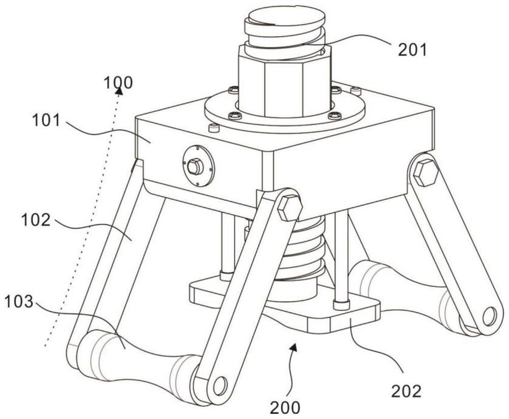
[0030] refer to figure 1 , the present embodiment provides a power transmission line conductor and ground wire connection tube correction device, which is used to correct the bent connection tube to a straight state, which is easy to use, and mainly includes a correction unit 100 and an adjustment unit 200; specifically, the correction unit 100, including a base 101, a correction rod 102, and a correction column 103. There are two pairs of correction rods 102, which are symmetrically connected to both ends of the base 101. The ends of the two pairs of correction rods 102 are hinged with a correction column 103. On the base 101 A through hole 101a is provided; the base 101 is used to carry the entire correction unit 100 and the adjustment unit 200, the correction rod 102 is rod-shaped, and can be fixed at both ends of the base 101 by welding, and the correction rod 102 is provided with two pairs of , and each team is located at both ends of the base 101, and the correction rods...

Embodiment 2

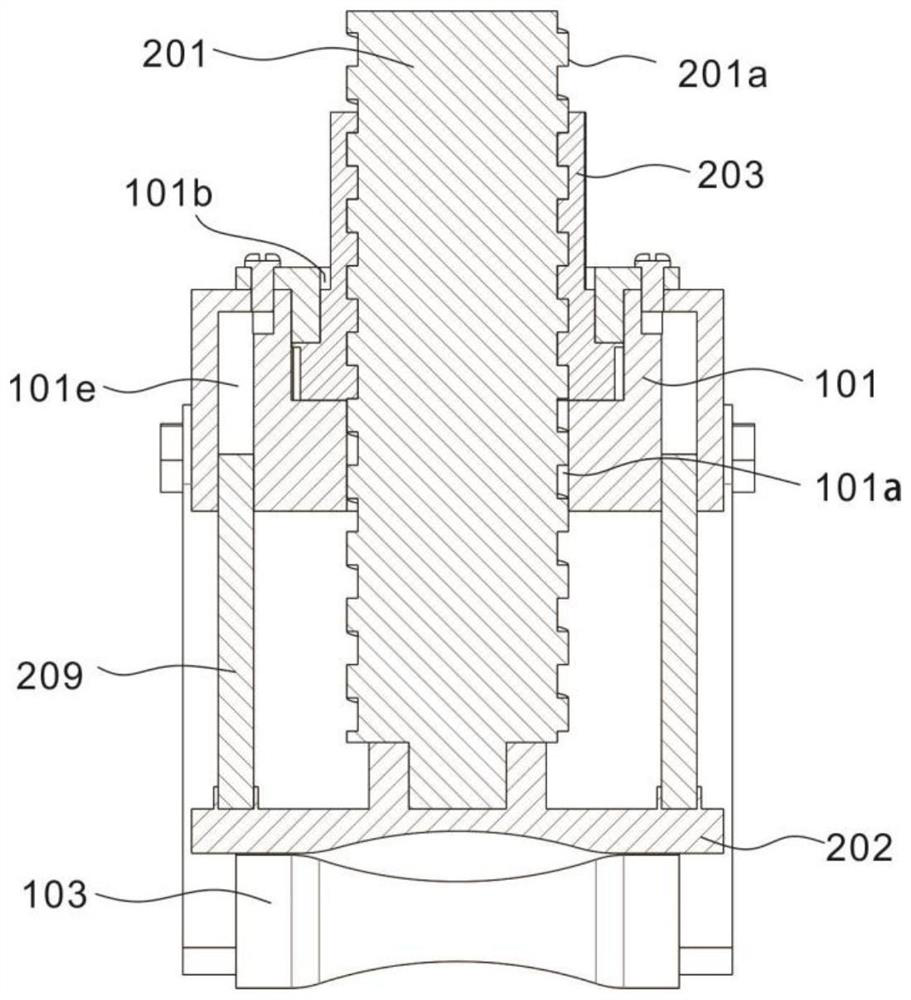
[0034] refer to Figure 1-7 , is the second embodiment of the present invention, this embodiment is based on the previous embodiment, and is different from the previous embodiment in that: in the process of rectifying the connecting pipe, sometimes a long period of rectification is required, but in embodiment 1 During the rectification process, the elastic force of the connecting tube may cause the adjustment rod 201 to loosen in the through hole 101a and the rectification fails. Therefore, this embodiment also provides a device capable of restricting the movement of the adjustment rod 201 during the correction, so as to prevent the adjustment rod 201 from loosening.

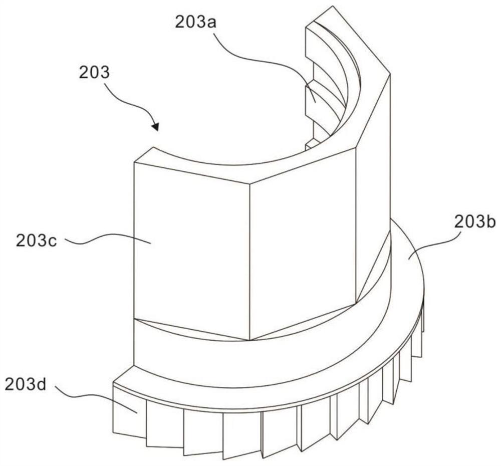
[0035] Specifically, the peripheral surface of the adjustment rod 201 is provided with an external thread 201a, and the adjustment unit 200 also includes a rotating member 203. The connection forms a screw action, wherein the adjusting rod 201 can only move along the axial direction of the through hole 101a, bu...


PUM


Abstract

The invention discloses a power transmission line ground wire splicing sleeve correction device. The power transmission line ground wire splicing sleeve correction device comprises a correction unit and an adjusting unit, and is characterized in that the correction unit comprises a base, two pairs of correction rods and correction columns, the two pairs of correction rods are symmetrically connected to the two ends of the base, the tail ends of the two pairs of correction rods are hinged with the correction columns, and a through hole is formed in the base; and the adjusting unit comprises anadjusting rod located in the through hole and a correction piece connected to one end of the adjusting rod, the two correction columns are located on the two sides of the correction piece, and the twocorrection columns and the correction piece are located on one side of the base. The device is simple to use, can be used on the ground and in the air, perfectly solves the problem that the traditional mode cannot be used in the air, can effectively reduce the damage, such as cracks and gaps, to the splicing sleeve in the correction process of a wire splicing sleeve, improves the construction quality of the splicing sleeve, and prolongs the service life of the splicing sleeve.

Description

technical field [0001] The invention relates to the field of power transmission and distribution lines, in particular to a correction device for a ground wire connecting pipe of a power transmission line. Background technique [0002] The length of high-voltage transmission line conductors (LGJ) and lightning conductors (GJ) is usually 2000 meters per piece during production, and a single conductor or lightning conductor cannot meet the needs of laying high-voltage transmission lines. The same-phase conductor or lightning conductor in the middle of the base tower is connected, and the connected fitting is the connecting pipe. The crimping of the ground wire is sometimes on the ground and sometimes in the air, often due to the uneven technical level of the operators, heavy equipment, poor crimping position in the air, difficult construction, operators who did not follow the technical regulations, and the connecting pipe under stress Unequal reasons lead to serious bending of...

Claims


Application Information

Patent Timeline
Patent Type & Authority Applications(China)
IPC IPC(8): B21D3/05B21D3/00
CPCB21D3/05B21D3/00
Inventor 刘鹏刘佳胡凯强盛兴隆李朝举甄玲玉刘佩垚王颖郭举富漆万碧吴聪聪陆禹初刘栖晏青樊丽萍任华夏李瑾陈乐黄辉高惠
Owner GUIZHOU POWER GRID CO LTD
Why Eureka
Try Eureka