Focusing and zooming control system of integrated optical equipment

A technology for optical equipment and control systems, which can be used in parts of TV systems, parts of TVs, and color TVs, etc., and can solve problems such as inability to ensure images.

Pending Publication Date: 2020-12-22
中山北方晶华精密光学有限公司
View PDF1 Cites 0 Cited by
  • Summary
  • Abstract
  • Description
  • Claims
  • Application Information

AI Technical Summary

Problems solved by technology

The integrated optical equipment focal length adjustment system in the above patent has the following disadvantages: although the acquisition equipment can be adjusted in focus, it cannot ensure that the image after the acquisition equipment is focused is the clearest image

Method used


Image

  • Focusing and zooming control system of integrated optical equipment
  • Focusing and zooming control system of integrated optical equipment
  • Focusing and zooming control system of integrated optical equipment

Examples


Embodiment 1

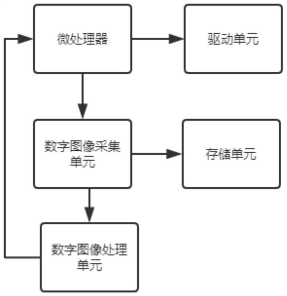
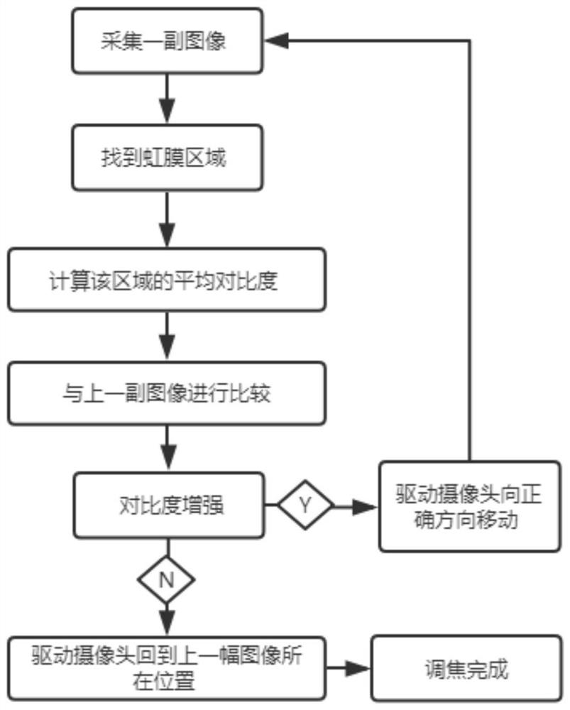
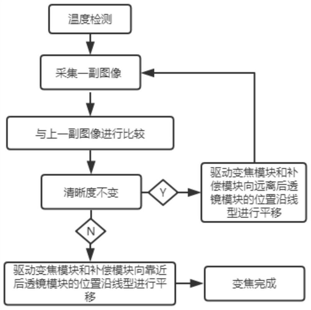
[0027] An integrated optical device focus and zoom control system, such as Figure 1-3 As shown, it includes a microprocessor, a digital image acquisition unit, a digital image processing unit, a storage unit and a drive unit, and the microprocessor is a control center; the signal output end of the digital image acquisition unit is connected with the digital image processing unit The signal output end of the digital image processing unit is connected to the microprocessor in communication; the switch control end of the drive unit is electrically connected to the microprocessor; the signal input end of the storage unit is connected to the digital image acquisition unit in communication, and the digital image The images collected by the collection unit are processed by the digital image processing unit and then recorded into the storage unit.

[0028] The digital image acquisition unit includes a camera and an infrared illuminator. The camera is a structure for shooting images, ...

Embodiment 2

[0037] An integrated optical device focus and zoom control system, such as Figure 1-3 As shown, it includes a microprocessor, a digital image acquisition unit, a digital image processing unit, a storage unit and a drive unit, and the microprocessor is a control center; the signal output end of the digital image acquisition unit is connected with the digital image processing unit The signal output end of the digital image processing unit is connected to the microprocessor in communication; the switch control end of the drive unit is electrically connected to the microprocessor; the signal input end of the storage unit is connected to the digital image acquisition unit in communication, and the digital image The images collected by the collection unit are processed by the digital image processing unit and then recorded into the storage unit.

[0038] The digital image acquisition unit includes a camera and an infrared illuminator. The camera is a structure for shooting images, ...


PUM


Abstract

The invention discloses an focusing and zooming control system of integrated optical equipment, relates to the technical field of optical control, and aims to solve the problem that it cannot be ensured that a focused image is the clewest image. The system specifically comprises a microprocessor, a digital image acquisition unit, a digital image processing unit, a storage unit and a driving unit,the microprocessor is a control center; the signal output end of the digital image acquisition unit is in communication connection with the digital image processing unit, and the signal output end ofthe digital image processing unit is in communication connection with the microprocessor; and the switch control end of a driving unit is electrically connected with the microprocessor. The digital image acquisition unit is driven by the driving unit to move within a small range, continuously acquires images, performs image quality evaluation on a series of acquired images through the digital image processing unit, judges whether an iris part is imaged clearly or not, completes a focusing process, and thus, obtains the clewest image through comparison.

Description

technical field [0001] The invention relates to the field of optical control technology, in particular to an integrated optical device focus adjustment and zoom control system. Background technique [0002] The existing focal length adjustment system of optical equipment generally provides rotational power through a motor, and then converts the rotational power into linear motion power through a secondary transmission mechanism to push the optical lens (group), thereby realizing the function of focusing / zooming. At present, most of the dimming and focusing systems of optical lenses in practical applications rotate the lens cam, and the grooves on the cam drive the lens in the lens to move, thereby realizing the functions of focusing and dimming of the lens. The mechanical structure of this dimming and focusing method is complicated, and the requirements for mechanical designers are relatively high. During operation, the error caused by the large return distance difference of...

Claims


Application Information

Patent Timeline
Patent Type & Authority Applications(China)
IPC IPC(8): H04N5/232
CPCH04N23/67
Inventor 袁志峰秦朝锋汤华锡胡书贤石妹吴志坚阳术刚
Owner 中山北方晶华精密光学有限公司
Why Eureka
Try Eureka