Small-leakage-rate positive-pressure leakage hole calibration method and device

A technology of positive pressure leaks and calibration methods, applied in measuring devices, by measuring the acceleration and deceleration rates of fluids, instruments, etc., can solve the problems of many gas molecules, low efficiency, and great influence of pressure and temperature, so as to shorten the time interval, Accurate detection results and improved accuracy

Pending Publication Date: 2020-12-22
SHANGHAI INST OF MEASUREMENT & TESTING TECH
View PDF0 Cites 2 Cited by
  • Summary
  • Abstract
  • Description
  • Claims
  • Application Information

AI Technical Summary

Problems solved by technology

[0007] 2. Due to the internal pressure of the positive pressure leak hole is 1×10 5 Above Pa, there are many gas molecules, and the pressure is greatly affected by temperature.
Therefore, the virtual leakage caused by the pressure change at the outlet end of the positive pressure leak caused by the temperature change of the calibration is the main problem affecting the lower limit and accuracy of the measurement.
Although in the calibration work, the method of measuring the virtual leakage first and then deducting it can be used to improve the lower limit of measurement, but the temperature change is still an important factor affecting the lower limit of measurement and accuracy
[0008] 3. There are many kinds of gases inside the positive pressure standard leak, and different gases are likely to react when they are mixed together. When the traditional positive pressure leak calibration device detects a leak and continues to detect another leak of a different gas, at least It takes 4 hours to wait for the gas to stabilize before starting the measurement, which is less efficient

Method used


Image

  • Small-leakage-rate positive-pressure leakage hole calibration method and device
  • Small-leakage-rate positive-pressure leakage hole calibration method and device
  • Small-leakage-rate positive-pressure leakage hole calibration method and device

Examples


Embodiment Construction

[0033] The present invention will be further described below in conjunction with the accompanying drawings and specific embodiments.

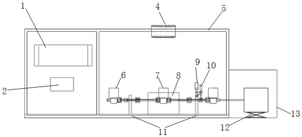
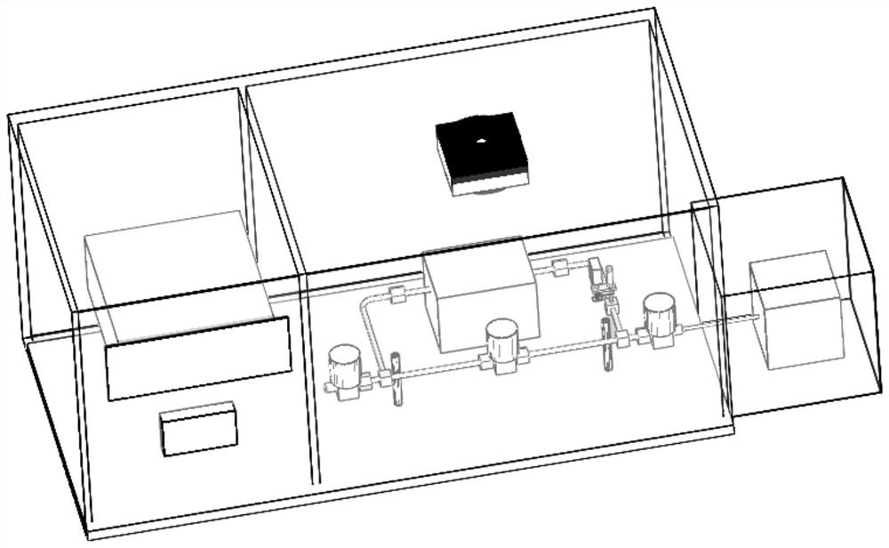
[0034] see Figure 1-2 , Figure 1-2 Schematic diagram of the self-developed positive pressure leak calibration device. It is mainly composed of a volume measurement system composed of a capacitive scale and a piston, a constant temperature system composed of a semiconductor refrigeration module and a PID control, a differential pressure film gauge, three high-precision pneumatic surface sealing valves and a vacuum pipeline. Among them, the pipeline between the differential pressure film gauge, the test valve and the shut-off valve forms the calibration room, and the pipeline between the differential pressure film gauge, the vent valve and the shut-off valve forms the reference room.

[0035] The traditional positive pressure leak calibration method is to connect the leak to be calibrated with the calibration chamber. As the gas leaks into th...


PUM


Abstract

The invention relates to a small-leakage-rate positive-pressure leakage hole calibration method which comprises the following steps: arranging a calibration chamber and a reference chamber made of thesame material as the calibration chamber, and separating the calibration chamber from the reference chamber by a differential pressure film gauge and a stop valve; the gas quantity Q.t being in direct proportion to the reading P of the differential pressure film gauge, so that a formula can be obtained, wherein Q represents the leakage rate, t represents the time, and k is equal to P0* x.A / (P2-P1); arranging a piston in the calibration chamber, and calculating the volume coefficient k by measuring the pressure difference caused by pushing the piston, the pressure difference being equivalent to the amount of gas flowing into the leakage hole, wherien the A is the sectional area of the piston, x is the moving distance of the piston, and P1 and P2 are indicating values of the film meters before and after the piston moves; and measuring the change rate of the pressure P along with the time t caused by the fact that the hole to be detected flows into the calibration chamber, thereby obtaining the leakage rate of the hole to be detected.

Description

technical field [0001] The invention relates to a small leak rate positive pressure leak calibration method and device, belonging to the technical field of vacuum measurement. Background technique [0002] Positive pressure leak is the leak rate standard in positive pressure leak detection, and its leak rate accuracy is directly related to the leak detection sensitivity and effectiveness of the leak detector. Therefore, calibration of positive pressure leaks is critical. [0003] The working principles of related positive pressure leak calibration devices in the prior art are divided into constant pressure method and constant volume method. Under the condition of constant temperature, the gas volume is represented by the product PV of the pressure P and the volume V. At this time, the leakage rate Q of the leak hole is the total differential of PV to time t, namely: If the volume remains constant, it is a constant volume method; if the pressure remains constant, it is a c...

Claims


Application Information

Patent Timeline
Patent Type & Authority Applications(China)
IPC IPC(8): G01M3/00G01M3/26
CPCG01M3/007G01M3/26
Inventor 刘贝贝许红张忠立王灿张斯宏金愿
Owner SHANGHAI INST OF MEASUREMENT & TESTING TECH
Why Eureka
Try Eureka