Fireproof structure and installation method for smoke prevention and exhaust duct

A technology of fireproof structure and installation method, applied in the direction of pipes, applications, rigid pipes, etc., can solve the problems of not being able to ensure life safety well, and the fire resistance limit of smoke and exhaust ducts is short, so as to achieve tight packaging and improve heat resistance , the effect of tight connection

Active Publication Date: 2022-02-01
昆山市城乡建设有限公司
View PDF0 Cites 0 Cited by
  • Summary
  • Abstract
  • Description
  • Claims
  • Application Information

AI Technical Summary

Problems solved by technology

[0004] In view of the related technologies mentioned above, the inventor believes that since the fire resistance limit of the smoke prevention and exhaust duct is extremely short, if only the smoke prevention and exhaust duct is used for the smoke prevention and exhaust work, people's life safety cannot be well guaranteed in the event of a fire

Method used


Image

  • Fireproof structure and installation method for smoke prevention and exhaust duct
  • Fireproof structure and installation method for smoke prevention and exhaust duct
  • Fireproof structure and installation method for smoke prevention and exhaust duct

Examples


Embodiment 1

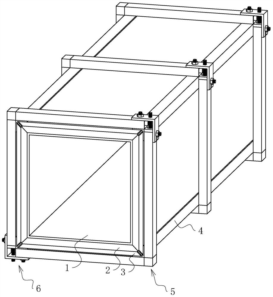
[0058] refer to figure 1 , a fireproof structure for the smoke prevention and exhaust air duct, including several sections of heat insulation layers wrapped on the outer surface of the smoke prevention and exhaust air duct 1, the heat insulation layer is specifically rock wool material, and the several sections of heat insulation layers are arranged with equal lengths. Taking one section of the heat insulation layer as an example, each section of the heat insulation layer is wrapped with four fireproof boards 3 and four edge strips 4, and each section of the heat insulation layer is provided with three fixing devices for fixing the heat insulation layer , the three fixing devices are respectively located at the two ends and the middle of the corresponding smoke prevention and exhaust duct 1 .

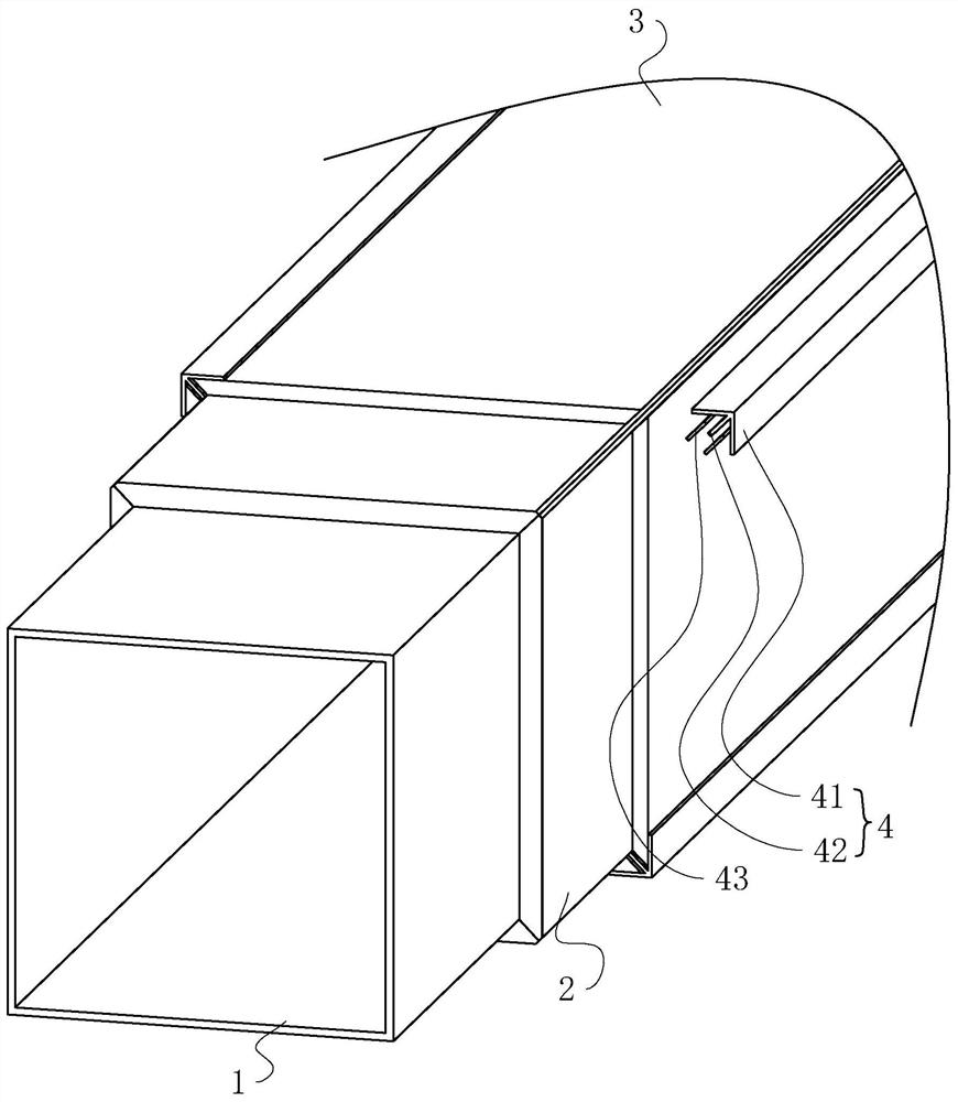
[0059] refer to figure 2 , the length of each section of heat insulation layer can be set between 0.8m and 1.2m according to the actual situation, each section of heat insulation laye...

Embodiment 2

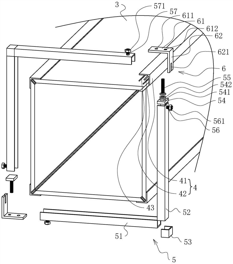
[0070] The difference between this embodiment and embodiment 1 is: refer to Figure 4 , each connecting piece 6 includes a first stabilizing plate 63 and a second stabilizing plate 64 . The second C-shaped steel 52 in each fixture 5 is fixedly connected with a fixed screw rod 58 on the end face away from the first C-shaped steel 51, and the fixed screw rod 58 is threaded with a fixed nut 581; the first C-shaped steel in each fixed piece 5 The side of the end of the section steel 51 away from the second C-section steel 52 is fixedly connected with a stabilizing screw 59 , and the stabilizing screw 59 is threaded with a stabilizing nut 591 .

[0071] refer to Figure 4 A groove 7 is provided on the side of the second C-shaped steel 52 in each fixture 5 away from the end of the first C-shaped steel 51, and a spring 71 is fixedly connected to the groove bottom of the groove 7, and the spring 71 is far away from the groove 7. One end of the bottom of the groove is fixedly connect...


PUM


Abstract

This application relates to the field of fire prevention and smoke exhaust, in particular to a fireproof structure for smoke prevention and exhaust ducts, which includes several sections of heat insulation layers wrapped on the outer surface of smoke prevention and exhaust ducts, several sections of heat insulation layers, etc. Long installation; each section of the heat insulation layer is provided with a number of fixing devices for fixing the heat insulation layer, and the number of fixing devices are evenly distributed on the corresponding smoke exhaust duct. The present application has a better effect of realizing the protection of people's life safety.

Description

technical field [0001] The present application relates to the field of fire prevention and smoke exhaustion, in particular to a fireproof structure for a smoke prevention and exhaust air duct and an installation method thereof. Background technique [0002] The function of the smoke prevention and exhaust system mainly has two aspects: one is to set up smoke prevention facilities in evacuation passages and densely populated areas, which is conducive to the safe evacuation of personnel; obstacles. At present, people have higher and higher requirements for building safety, and the heat insulation and fire prevention performance of the smoke control system is an important guarantee for building safety. [0003] Conventional fire prevention and smoke exhaust ducts are mostly made of galvanized steel sheets, and their fire resistance limit is only 0.25 hours. [0004] In view of the related technologies mentioned above, the inventor believes that since the fire resistance limit...

Claims


Application Information

Patent Timeline
Patent Type & Authority Patents(China)
IPC IPC(8): F16L9/22F16L57/04F16L59/02F16L59/12F24F13/02
CPCF16L9/003F16L9/22F16L57/04F16L59/025F16L59/028F16L59/12F16L59/123F24F13/0245F24F13/0263F24F13/0281
Inventor 陈卫根徐建明胡瑞邵明峦沈学文
Owner 昆山市城乡建设有限公司
Why Eureka
Try Eureka