
CPU clamping device for CPU taking and placing module

A clamping device and module technology, applied in the field of CPU, can solve the problems of falling CPU module, lack of protective structure, damage to CPU module, etc.

Pending Publication Date: 2020-12-22
江苏汤谷智能科技有限公司
View PDF0 Cites 2 Cited by
  • Summary
  • Abstract
  • Description
  • Claims
  • Application Information

AI Technical Summary

Problems solved by technology

[0003] The current CPU module pick-and-place structure is relatively simple. Usually, the CPU module is picked up by hand or with some small tools, such as tweezers and other tools. Because there is no protective structure, the CPU module is easily damaged. The CPU module will be damaged, so it is necessary to add a clamping device to the CPU module, which is convenient for the CPU module to be taken and placed more safely, so that the CPU module is not easy to be damaged. At the same time, a method for CPU removal is proposed The CPU clamping device of the module is convenient to better solve the above-mentioned problems

Method used


Image

  • CPU clamping device for CPU taking and placing module
  • CPU clamping device for CPU taking and placing module
  • CPU clamping device for CPU taking and placing module

Examples


Embodiment Construction

[0019] In order to make the object, technical solution and advantages of the present invention clearer, the present invention will be further described in detail below in conjunction with the accompanying drawings and embodiments. It should be understood that the specific embodiments described here are only used to explain the present invention, not to limit the present invention.

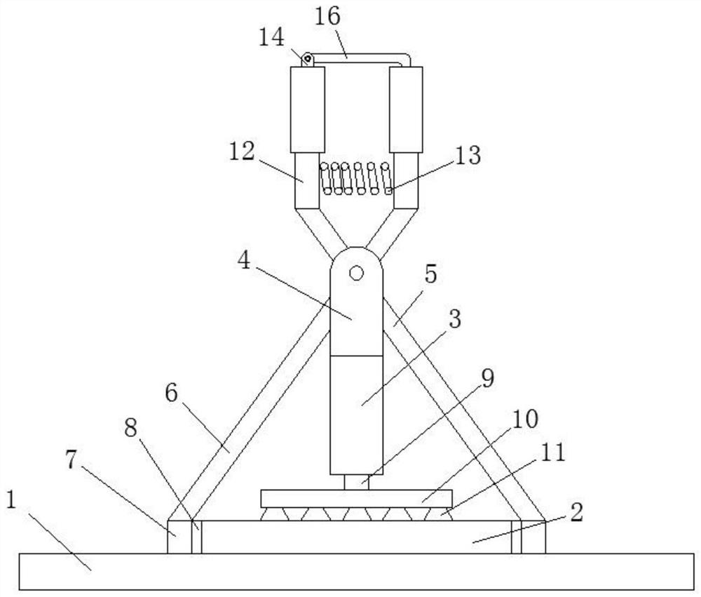
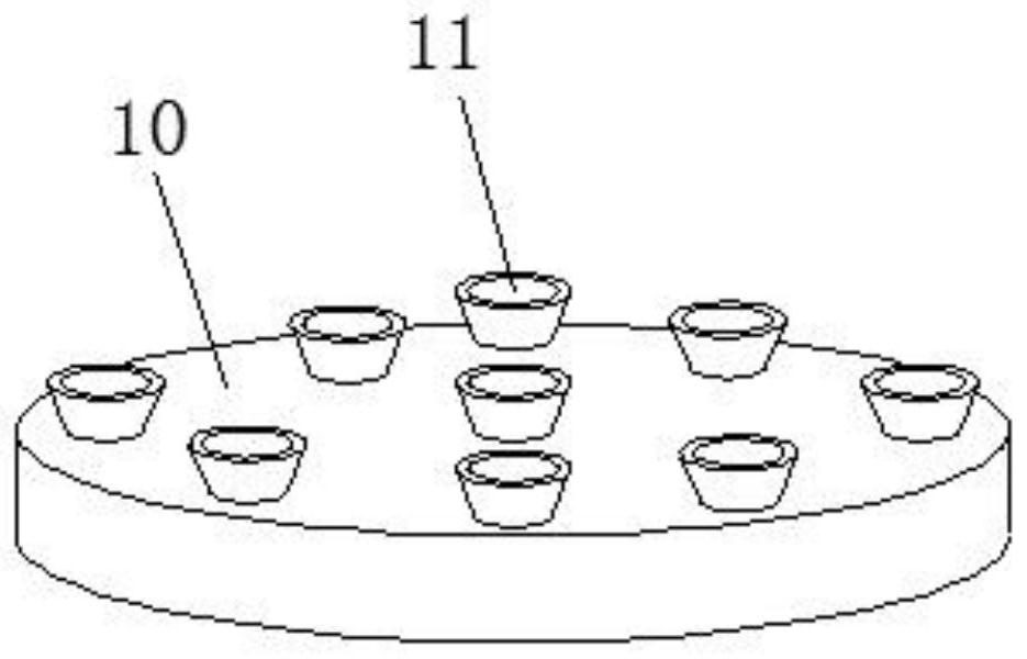
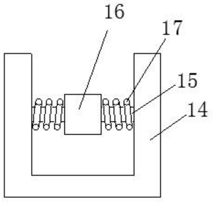
[0020] refer to Figure 1-3 , a CPU clamping device for CPU pick-and-place modules, including a main board 1, a CPU module body 2 is installed on the top of the main board 1, a fixing column 3 is arranged on the top of the CPU module body 2, and the bottom of the fixing column 3 Internally threaded holes are provided, and the top of the fixed column 3 is fixedly equipped with a mounting part 4, so that the right support rod 5 and the left support rod 6 can be flipped inside the mounting part 4, and the right support rod 5 and the left support rod 6 can be rotated. To close and open, the mounting p...


PUM


Abstract

The invention discloses a CPU clamping device for a CPU taking and placing module. The CPU clamping device comprises a mainboard, wherein a CPU module body is mounted at the top of the mainboard, a fixed column is arranged at the top of the CPU module body, a mounting piece is fixedly mounted at the top of the fixed column, a right supporting rod and a left supporting rod are hinged to the inner side of the mounting piece, and limiting plates are fixedly mounted at the lower ends of the right supporting rod and the left supporting rod. According to the CPU clamping device, since the mounting piece is fixedly mounted at the top of the fixed column, the right supporting rod and the left supporting rod can conveniently perform turnover movement in the mounting piece, and then the right supporting rod and the left supporting rod can be closed and opened; and since the limiting plates are fixedly mounted at the lower ends of the right supporting rod and the left supporting rod, the limitingplates conveniently drive buffer pads to extrude the two sides of the CPU module body, at the moment, the CPU module body is better limited at the inner sides of the buffer pads under the action of the right supporting rod and the left supporting rod, and meanwhile the buffer pads can protect the CPU module body and achieve protection and anti-skid effects on the CPU module body.

Description

technical field [0001] The invention belongs to the technical field of CPUs, in particular to a CPU clamping device for a CPU pick-and-place module. Background technique [0002] The central processing unit (CPU, Central Processing Unit) is a very large-scale integrated circuit, which is the computing core (Core) and control core (Control Unit) of a computer. Its function is mainly to interpret computer instructions and process data in computer software. The CPU can be logically divided into three modules, which are the control unit, the computing unit and the storage unit, and these three parts are connected by the CPU internal bus. [0003] The current CPU module pick-and-place structure is relatively simple. Usually, the CPU module is picked up by hand or with some small tools, such as tweezers and other tools. Because there is no protective structure, the CPU module is easily damaged. The CPU module will be damaged, so it is necessary to add a clamping device to the CP...

Claims


Application Information

Patent Timeline
Patent Type & Authority Applications(China)
IPC IPC(8): B25B11/00
CPCB25B11/007
Inventor 刘兴茂
Owner 江苏汤谷智能科技有限公司
Learn More