
Side vertical fast charging connector

A connector, side vertical technology, applied in the field of side vertical fast charging connectors, can solve the problems of EMI, poor waterproof and anti-fouling performance, terminal signal crosstalk and other problems that affect the service life, and achieve improved crosstalk and dimensional consistency Good, the effect of preventing the exposure of electromagnetic waves

Pending Publication Date: 2020-12-18
东莞市光杰电子科技有限公司
View PDF0 Cites 0 Cited by
  • Summary
  • Abstract
  • Description
  • Claims
  • Application Information

AI Technical Summary

Problems solved by technology

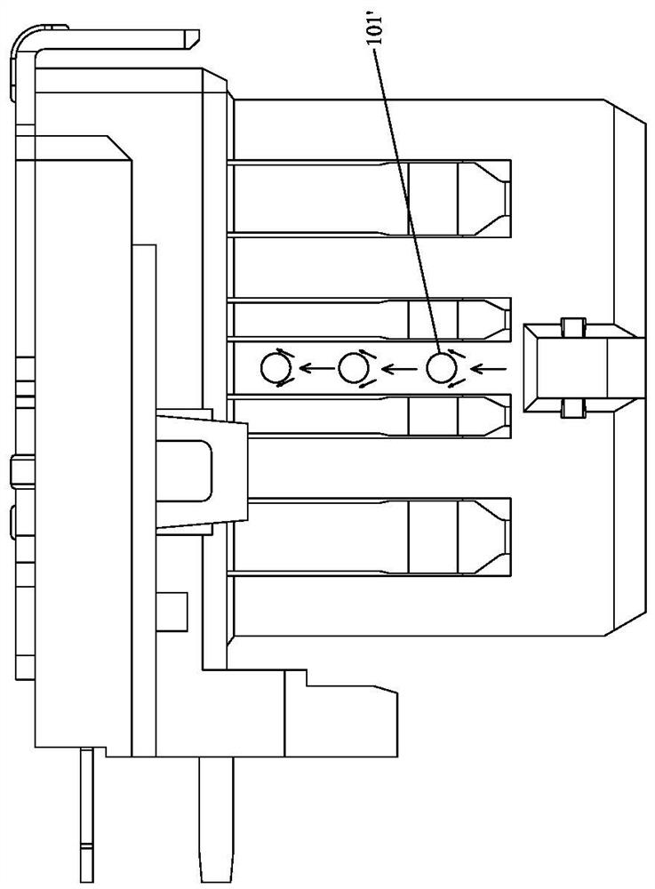
[0010] In view of this, the present invention aims at the deficiencies in the prior art, and its main purpose is to provide a side-mounted fast-charging connector, which effectively solves the problem of not being easy to fill the mold during injection molding, and solves the problem of signal crosstalk between terminals. Problems, solve the problems that the plug-in ends of multiple conductive terminals are completely exposed, which affects the service life and the EMI effect is poor, and solve the problems that the terminals are easy to cause pins and poor waterproof and anti-fouling performance

Method used


Image

  • Side vertical fast charging connector
  • Side vertical fast charging connector
  • Side vertical fast charging connector

Examples


Embodiment Construction

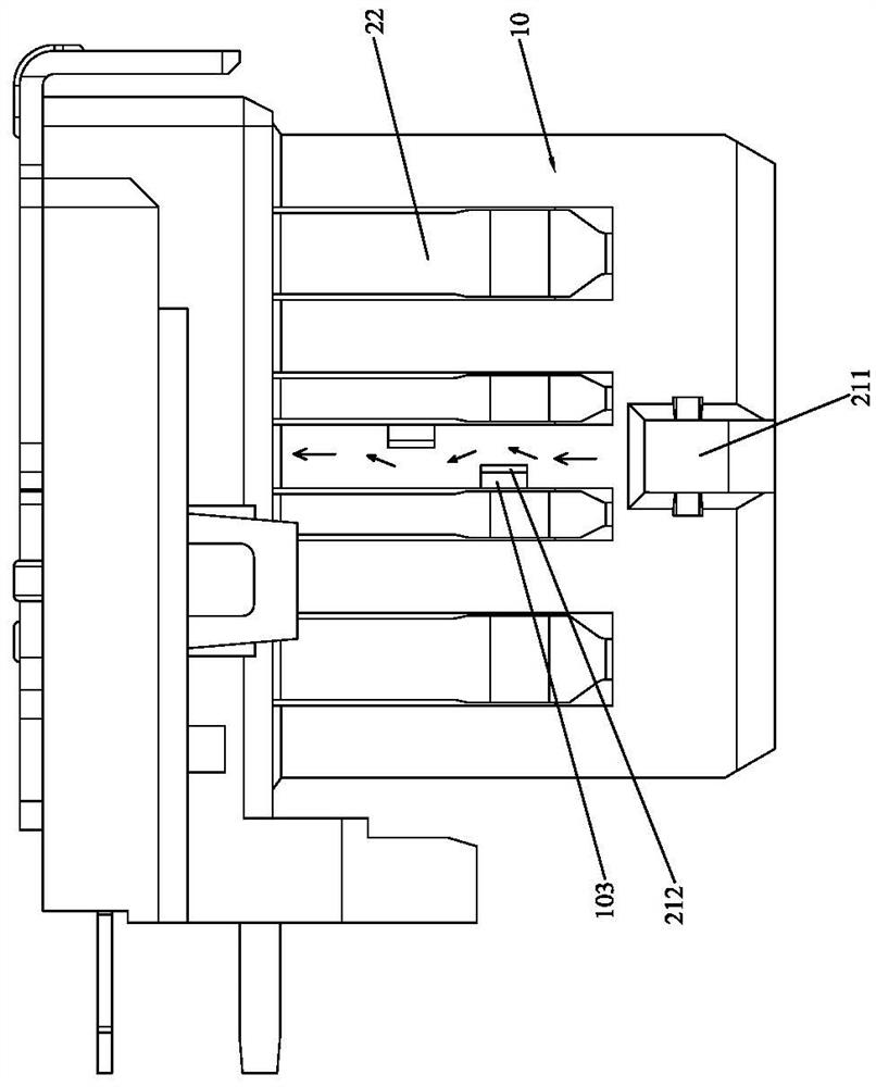
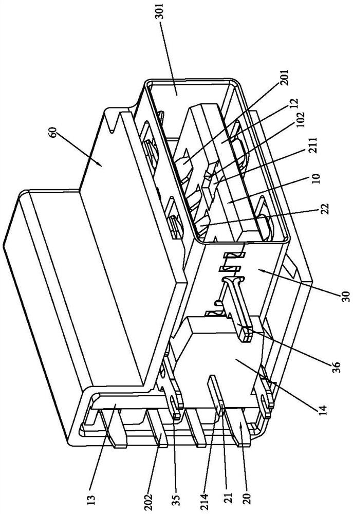
[0071] Please refer to Figure 2 to Figure 9 As shown, it shows the specific structure of the preferred embodiment of the present invention, including an insulating body 10 , a plurality of terminals 20 and a shielding case 30 .

[0072] The insulating main body 10 includes a base 11 and a tongue 12 integrally formed and connected, and a raised portion 13 extends upward from the top surface of the base 11 , and the raised portion 13 protrudes upwards out of the shielding shell 30 . A row of end spaces 101 are recessed on the raised portion 13 and the rear side of the base 11 . And the front side of the base 11 has a mounting plate 14 extending forward. The inner side of the mounting plate 14 has a step 141. The rear side of the shielding shell 30 is positioned against the step 141, so that the shielding shell 30 is assembled. more convenient.

[0073] The plurality of terminals 20 are disposed on the insulating body 10 , the contact ends 201 of the plurality of terminals 20 ...


PUM


Abstract

The invention discloses a side vertical fast charging connector. The top surface of a base extends upwards to form a heightening part, and a fast charging terminal comprises a flat contact part, a main body part, a connecting part and a plugging part which are integrally connected in sequence; the main body part is embedded in the tongue plate, the upper surface of the front end of the tongue plate is concavely provided with two fixed end holes which are longitudinally arranged at intervals, the two fixed end holes are arranged in a left-right staggered manner, and the front ends of the contact ends of the plurality of conductive terminals are propped against the hanging table; the tail ends of the plugging ends of the plurality of conductive terminals extend out of the same outer side ofthe base and the heightening part in a row; a sealing plate is arranged in the row end space and covers the plugging ends of the plurality of conductive terminals; and the outer surface of the sealingplate is covered with an EMI shielding sheet, and the shielding shell and the heightening part are wrapped with an outer shell. The problems that mold saturation and signal crosstalk are not easy during injection molding, the service life is affected, the EMI effect is poor, the terminal is prone to causing Pin collapse, and the waterproof and antifouling performance is poor are solved.

Description

technical field [0001] The invention relates to the technology in the field of connectors, in particular to a side-standing fast charging connector. Background technique [0002] With the continuous update and development of electronic products, electronic products are also becoming more and more popular in life, and consumers' demand for miniaturization of electronic products is increasing. The USB electrical connector has gradually become the development trend of modern data transmission due to its advantages of fast, plug-and-play, and convenient installation. At present, USB electrical connectors have become the mainstream interface for computers, mobile phone chargers, and car chargers. With the further improvement of USB interface technology, the application of USB interface technology will be further expanded. [0003] At present, the existing electrical connectors are divided into two types: flat electrical connectors and side plug-in electrical connectors. Among t...

Claims


Application Information

Patent Timeline
IPC IPC(8): H01R13/502H01R12/71H01R13/02H01R13/50H01R13/516H01R13/52H01R13/6461H01R13/6581
CPCH01R12/716H01R13/02H01R13/50H01R13/502H01R13/516H01R13/52H01R13/5213H01R13/6461H01R13/6581
Inventor 罗词贵
Owner 东莞市光杰电子科技有限公司
Learn More