Diffracted optical waveguide, manufacturing method, and method and device for improving uniformity of emergent light

A technology of uniformity and outgoing light, applied in the field of optical imaging, can solve the problems of no mass production feasibility, limited improvement effect, difficult design of gratings, etc., and achieve the effect of low price, improved uniformity of outgoing light, and uniform brightness of light.

Pending Publication Date: 2020-12-18
GOERTEK OPTICAL TECH CO LTD
View PDF7 Cites 4 Cited by
  • Summary
  • Abstract
  • Description
  • Claims
  • Application Information

AI Technical Summary

Problems solved by technology

But this kind of grating is difficult to design and process, and it is not feasible for mass production; the second is to change the grating period, but the improvement effect of this method is limited

Method used


Image

  • Diffracted optical waveguide, manufacturing method, and method and device for improving uniformity of emergent light
  • Diffracted optical waveguide, manufacturing method, and method and device for improving uniformity of emergent light
  • Diffracted optical waveguide, manufacturing method, and method and device for improving uniformity of emergent light

Examples


Embodiment Construction

[0035] Specific embodiments of the present invention will be described in detail below in conjunction with the accompanying drawings.

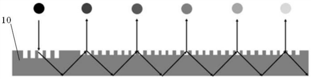
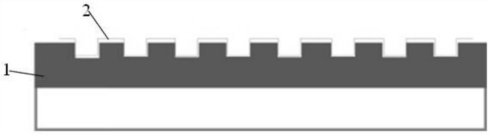
[0036] figure 2 is a schematic diagram of a diffractive optical waveguide that improves the uniformity of outgoing light according to the present invention, as figure 2 As shown, the diffractive optical waveguide 10 includes a diffraction grating 1 and a graded refractive index film 2 coated on the diffraction grating, and the uniformity of the brightness of the outcoupled light is improved by changing the refractive index of the graded refractive index film 2 in different outcoupling regions , preferably, the refractive index of the gradient index film becomes larger along the pupil expansion direction, the larger the refractive index of the gradient index film is, the greater the brightness of the outcoupled light, that is to say, the gradient index film at the front end of the pupil expansion direction The reduction of the refractive ind...


PUM


Abstract

The invention provides a diffracted optical waveguide, a manufacturing method, a method for improving the uniformity of emergent light and head-mounted display equipment, the diffracted optical waveguide comprises a diffraction grating and a refractive index gradient film coated on the diffraction grating, and the uniformity of the brightness of the coupled light is improved through the refractiveindex change of the refractive index gradient film in different coupled-out areas. According to the diffracted optical waveguide and the method, on the premise that grating design parameters are notchanged, the brightness of light coupled by the optical waveguide is uniform by using the head-mounted display equipment.

Description

technical field [0001] The present invention relates to the field of optical imaging technology, and more specifically, to a diffractive optical waveguide that improves the uniformity of outgoing light and a manufacturing method thereof, a method for improving the uniformity of outgoing light from a diffractive optical waveguide, and a head-mounted display device. Background technique [0002] The existing diffractive optical waveguide structure optical path is mostly used in surface relief grating (Surface relief grating, SRG). Surface relief gratings are usually scribed on the substrate or embossed by photolithography, and are divided into one-dimensional gratings and two-dimensional gratings. However, both are uniform gratings, and the grating constant and grating depth are the same. Due to their own characteristics, the light energy in the outcoupling region will become more and more Low, resulting in uneven brightness of the outgoing light, the human eye will see a pat...

Claims


Application Information

Patent Timeline
Patent Type & Authority Applications(China)
IPC IPC(8): G02B6/124G02B5/18G02B27/01
CPCG02B6/124G02B5/1847G02B27/0172
Inventor 彭旭赵东峰董立超杜凯凯刘宝山刘艺朱春霖艾立夫
Owner GOERTEK OPTICAL TECH CO LTD
Why Eureka
Try Eureka