Energy-saving valve of efficient energy-saving heat pump

A high-efficiency energy-saving, energy-saving valve technology, applied in the direction of valve lifts, valve details, valve devices, etc., can solve the problems of inconvenient installation and disassembly, reduce the convenience of connecting energy-saving valves and pipelines, and reduce work efficiency, etc., to achieve convenient prediction Connection, stable and effective connection, and the effect of improving work efficiency

Inactive Publication Date: 2020-12-18
广州米粒科技有限公司
View PDF0 Cites 2 Cited by
  • Summary
  • Abstract
  • Description
  • Claims
  • Application Information

AI Technical Summary

Problems solved by technology

[0004] Aiming at the deficiencies of the prior art, the present invention provides an energy-saving valve for a high-efficiency energy-saving heat pump. The cooperation of bolts and nuts connects flanges and pipes. When disassembling or installing bolts and nuts, auxiliary tools are needed. Installation and disassembly are inconvenient, which reduces the convenience of connecting energy-saving valves to pipes and reduces work efficiency.

Method used


Image

  • Energy-saving valve of efficient energy-saving heat pump
  • Energy-saving valve of efficient energy-saving heat pump
  • Energy-saving valve of efficient energy-saving heat pump

Examples


Embodiment Construction

[0045] The following will clearly and completely describe the technical solutions in the embodiments of the present invention with reference to the accompanying drawings in the embodiments of the present invention. Obviously, the described embodiments are only some, not all, embodiments of the present invention. Based on the embodiments of the present invention, all other embodiments obtained by persons of ordinary skill in the art without making creative efforts belong to the protection scope of the present invention.

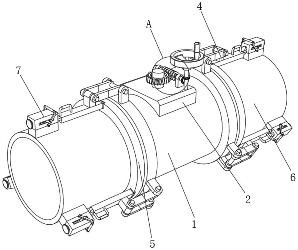
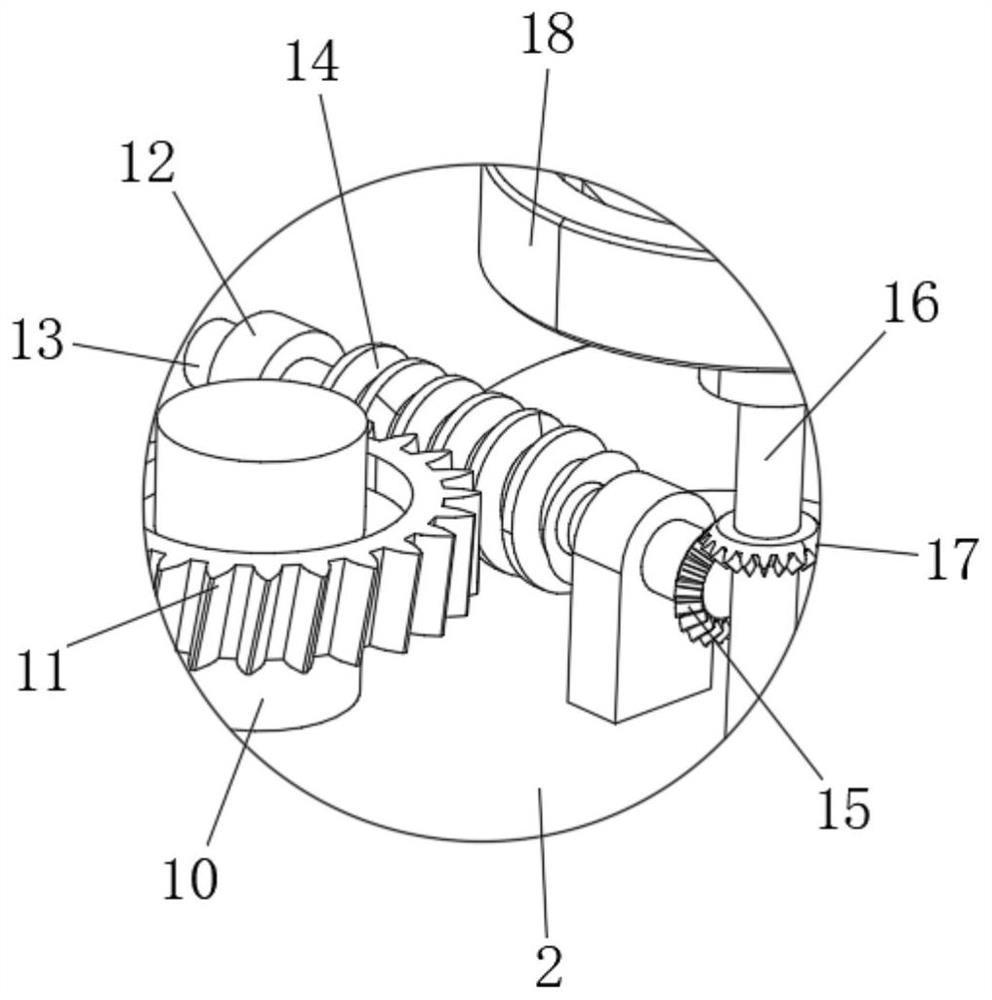
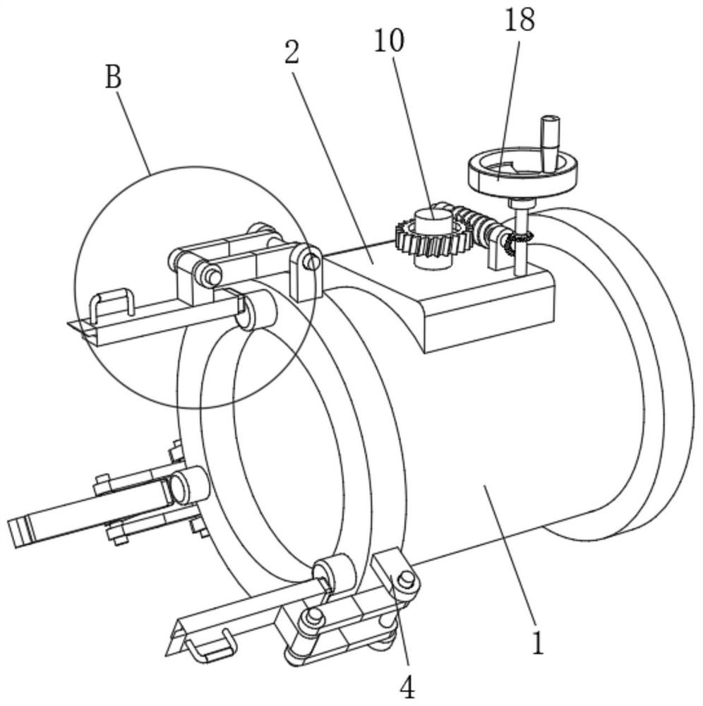
[0046] see Figure 1-6 , the present invention provides a technical solution: an energy-saving valve for a high-efficiency energy-saving heat pump, including a valve body 1, the left and right sides of the valve body 1 are fixedly connected with a positioning shaft 3, and the outer surface of the valve body 1 is provided with a locking device 4. The locking device 4 includes a first support block 401, the lower surface of the first support block 401 is fixedly...


PUM


Abstract

The invention relates to the technical field of energy-saving valves, and discloses an energy-saving valve of an efficient energy-saving heat pump. The energy-saving valve of the efficient energy-saving heat pump comprises a valve body; positioning shafts are fixedly connected to the left side surface and the right side surface of the valve body; a locking device is arranged on the outer surface of the valve body; circular ring plates are arranged on the left side surface and the right side surface of the valve body; pipelines are fixedly connected to the outer side surfaces of the circular ring plates; limiting devices are arranged on the outer surfaces of the pipelines; positioning grooves are formed in the inner side faces of the circular ring plates; and clamping grooves are formed inthe outer side faces of the circular ring plates. According to the energy-saving valve of the efficient energy-saving heat pump, by arranging first supporting blocks, first circular shafts, connectingrods, second circular shafts, second supporting blocks and grips, fixed pressing rods can be conveniently and effectively connected with the clamping grooves, so that the valve body, the circular ring plates and the pipelines can be more stably and effectively connected, the connecting mode does not need auxiliary tools; the pipelines and the valve body are convenient to mount, the convenience ofconnection of the valve body and the pipelines is greatly improved, and the working efficiency is greatly enhanced.

Description

technical field [0001] The invention relates to the technical field of energy-saving valves, in particular to an energy-saving valve for high-efficiency energy-saving heat pumps. Background technique [0002] The energy-saving valve is used in the steam pipe network and equipment. It can automatically discharge condensed water, air and other non-condensable gases, and prevent the leakage of water and steam. According to the different working principles of the valve, the valve can be converted into the following types. Mechanical Type: Action depends on the change of condensate level in the steam valve, including float type: the float is a closed hollow sphere with an open upward float type, the float is a barrel type with an upward open open downward float type, and the float is an open Downward barrel type, thermostatic type: action depends on the change of liquid temperature, including bimetallic sheet, the sensitive element is bimetallic sheet Vapor pressure type: the sen...

Claims


Application Information

Patent Timeline
Patent Type & Authority Applications(China)
IPC IPC(8): F16K1/22F16K1/226F16K1/50F16K31/53F16K31/44F16K27/02
CPCF16K1/221F16K1/226F16K1/50F16K27/0209F16K31/44F16K31/53
Inventor 卢林辉
Owner 广州米粒科技有限公司
Why Eureka
Try Eureka