
Vibration rod damping sleeve

A technology of vibrating rod and shock-absorbing sleeve, applied in the direction of spring/shock absorber, spring/shock absorber design features, coil spring, etc. effect, the effect of improving the vibrating effect

Active Publication Date: 2020-12-18
CHINA FIRST METALLURGICAL GROUP
View PDF5 Cites 0 Cited by
  • Summary
  • Abstract
  • Description
  • Claims
  • Application Information

AI Technical Summary

Problems solved by technology

The vibrating rod is based on high-frequency vibration, so it is very easy to damage the contact structure during work, and even damage the formwork to the tie rods, causing dangerous accidents such as running molds and exploding molds.

Method used


Image

  • Vibration rod damping sleeve
  • Vibration rod damping sleeve
  • Vibration rod damping sleeve

Examples


Embodiment 1

[0018] The technical solution of the present invention is: a vibrating rod shock-absorbing sleeve, such as figure 1 As shown, including a sleeve body 4, at least one shock absorbing assembly is arranged close to the inner wall of the sleeve body 4, the front end of the sleeve body 4 is provided with an opening 2 for the insertion of the vibrating rod 3, and the opening 2 and the tail end of the sleeve body 4 are provided There is a clamping assembly 5 for fixing the sleeve body 4 and the vibrating rod 3 .

[0019] Further, the shock absorbing assembly is sheathed on the outer wall of the vibrating rod 3 .

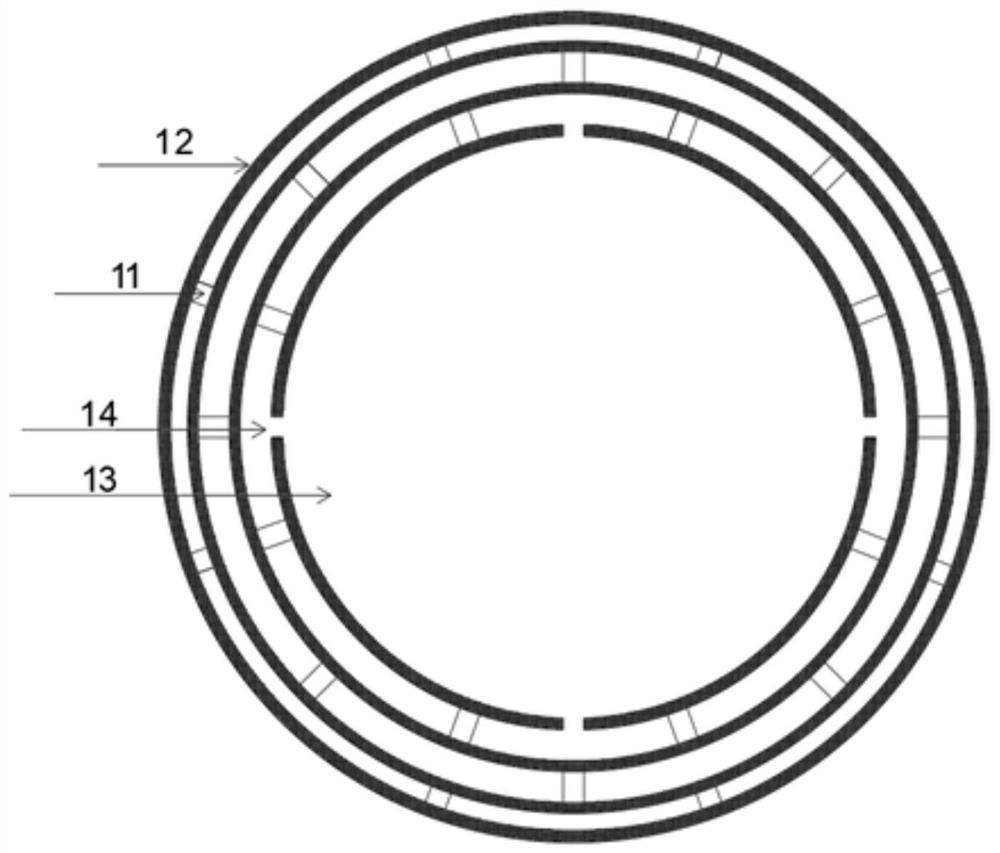
[0020] Furthermore, the shock absorbing assembly is a circular shock absorbing ring 1, such as figure 2 As shown, the circular damping ring 1 includes at least two coaxially arranged hard fixed rings 12 whose diameters gradually increase, and at least two elastic elements are equidistantly arranged between each hard fixed ring 12 11. The elastic element 11 has good elast...

Embodiment 2

[0024] The technical solution of the present invention is: a vibrating rod shock-absorbing sleeve, including a sleeve body 4, at least one shock-absorbing component is arranged close to the inner wall of the sleeve body 4, and the front end of the sleeve body 4 is provided with an opening for the insertion of the vibrating rod 3 2. The opening 2 and the tail end of the casing 4 are provided with a clamping assembly 5 .

[0025] Further, the shock absorbing assembly is sheathed on the outer wall of the vibrating rod 3 .

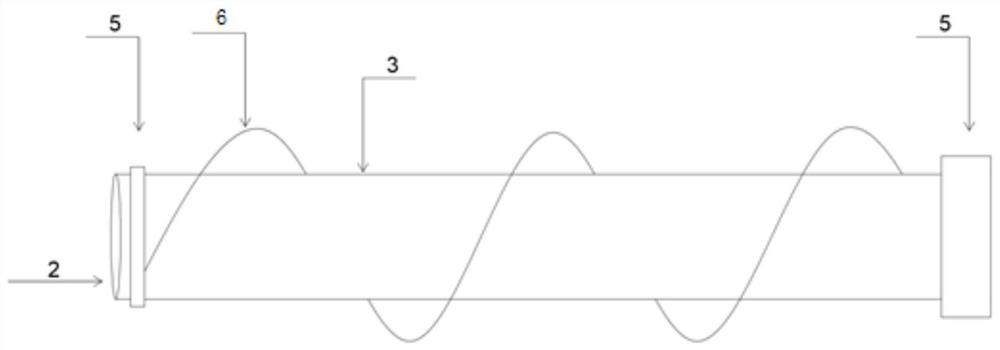
[0026] Furthermore, the shock absorbing assembly is a spiral shock absorbing ring 6, such as image 3 As shown, the helical shock absorbing ring 6 is a hard shock absorbing ring spirally wound on the outer wall of the vibrating rod 3, and the hard shock absorbing ring includes at least two coaxially arranged For large hard strips, a plurality of elastic elements 11 are equidistantly arranged in the circumferential direction between each hard strip, and each h...


PUM


Abstract

The invention discloses a vibration rod damping sleeve. The vibration rod damping sleeve comprises a sleeve body, wherein at least one damping assembly is arranged to be tightly attached to the innerwall of the sleeve body, an opening allowing a vibration rod to be inserted is formed in the front end of the sleeve body, and clamping assemblies are arranged at the opening and the tail end of the sleeve body. According to the vibration rod damping sleeve, under the condition that the vibration effect is hardly influenced, a good damping effect is achieved on structures such as steel bars makingcontact with the vibration rod damping sleeve; and two different structural forms are provided, the first structural form adopts a circular ring fixing method, and the structures are fixed in a plurality of mode, are mutually restricted and are firmer; and the second structural form adopts a spiral surrounding mode, so that the vibration rod damping sleeve is lighter and more economical, meanwhile, in the vibration process, concrete can be partially displaced, and the vibration effect is improved.

Description

technical field [0001] The invention relates to the field of construction tools, in particular to a shock-absorbing sleeve for a vibrating rod. Background technique [0002] In the process of concrete pouring, it is inevitable to use vibrating rods, and the vibrating rods are often in contact with important structures such as steel skeletons during use due to improper placement or special use scenarios. The vibrator works on the principle of high-frequency vibration, so it is very easy to damage the contact structure during work, and even damage the formwork to the tie rods, causing dangerous accidents such as running out of molds and exploding molds. Contents of the invention [0003] The object of the present invention is to provide a vibrating rod shock absorbing sleeve, which can exert a good shock absorbing effect on the contacted steel bar and other structures under the condition that the vibrating effect is hardly affected. [0004] In order to solve the above tech...

Claims


Application Information

Patent Timeline
IPC IPC(8): F16F3/00F16F1/12E04G21/08
CPCF16F3/00F16F1/12E04G21/08F16F2230/0035F16F2230/0041
Inventor 王洵方三陵熊浩滕飞刘体清吴盼
Owner CHINA FIRST METALLURGICAL GROUP
Learn More