
Torsional vibration isolator

A technology of isolators and elastic components, applied in the direction of spring/shock absorber, vibration suppression adjustment, mechanical equipment, etc., can solve the problems of reducing car ride comfort, uneven ignition, noise and vibration, etc., to improve ride comfort , Good shock absorption effect, the effect of reducing vibration

Active Publication Date: 2012-04-25
CHERY AUTOMOBILE CO LTD
View PDF5 Cites 7 Cited by
  • Summary
  • Abstract
  • Description
  • Claims
  • Application Information

AI Technical Summary

Problems solved by technology

[0002] The crankshaft in an automobile engine is a torsional elastic system, which itself has a certain natural vibration frequency. When the engine is working, the magnitude and direction of the force acting on the crankshaft change periodically. , torsional vibration occurs due to speed fluctuations, and the torsional vibration will be transmitted to the accessory system of the engine through the pulley and the belt, resulting in noise and vibration of the parts in the accessory system, which greatly reduces the ride comfort of the car, so there is an urgent need for a A torsional vibration isolator that can effectively solve the problem of crankshaft torsional vibration transmission to accessory gear trains

Method used


Image

  • Torsional vibration isolator
  • Torsional vibration isolator
  • Torsional vibration isolator

Examples


Embodiment 1

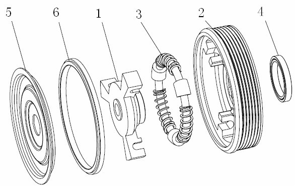
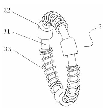
[0022] Such as Figure 1-5 As shown, the torsional vibration isolator of the present invention in this embodiment includes a driving disk 1, a driven disk hub 2 and an elastic damping unit 3, and the elastic damping unit 3 consists of a circular guide rail 31 and a number of evenly distributed on the guide rail 31 It consists of elastic parts; the middle part of the driving disc 1 is provided with a convex part 11, and the middle part of the convex part 11 is provided with a through hole 12. The outer periphery of the convex part 11 is press-fitted with a bearing 4, and the driving disc 1 is evenly distributed with three shift forks 13. The same side of the fork 13 is provided with a first groove 14; the number and position of the driven hub 2 are provided with ribs 21 corresponding to the shift fork 13, and the ribs 21 are all provided with a second groove 22 , the direction of the first groove 14 is opposite to that of the second groove 22; the outer circumference of the bea...


PUM


Abstract

The invention provides a torsional vibration isolator, which is used in engine crankshafts and the like, and can effectively solve the problem that crankshaft torsional vibration is transferred to an accessory gear train, thereby improving automotive ride comfort. The torsional vibration isolator comprises a driving disc, a driven disc hub and an elastic damping unit, wherein the elastic damping unit is composed of a circular guide rail and a plurality of elastic components uniformly distributed on the guide rail; a bulge is formed at the middle part of the driving disc; a through hole is formed at the middle part of the bulge, and a bearing is pressed and mounted at the periphery of the bulge; a plurality of shifting yokes are uniformly distributed on the driving disc, and each of the shifting yokes is respectively provided with a first groove at the same side; rib plates are arranged in the driven disc hub, both the number and the positions of the rib plates are corresponding to those of the shifting yokes, and each of the rib plates is respectively provided with a second groove; the first grooves and the second grooves are opposite to each other; the periphery of the bearing ispressed and mounted in the through hole at the center of the driven disc hub, the guide rail of the elastic damping unit is mounted in the first grooves and the second grooves, and the elastic components are distributed between the shifting yokes and the rib plates.

Description

technical field [0001] The invention belongs to the technical field of mechanical transmission, and in particular relates to a torsional vibration isolator. Background technique [0002] The crankshaft in an automobile engine is a torsional elastic system, which itself has a certain natural vibration frequency. When the engine is working, the magnitude and direction of the force acting on the crankshaft change periodically. , torsional vibration occurs due to speed fluctuations, and the torsional vibration will be transmitted to the accessory system of the engine through the pulley and the belt, resulting in noise and vibration of the parts in the accessory system, which greatly reduces the ride comfort of the car, so there is an urgent need for a A torsional vibration isolator that can effectively solve the problem of transmission of crankshaft torsional vibration to accessory gear trains. Contents of the invention [0003] The purpose of the present invention is to pr...

Claims


Application Information

Patent Timeline
IPC IPC(8): F16F15/133F16F15/137
Inventor 王超张欣林
Owner CHERY AUTOMOBILE CO LTD
Learn More