
Heating type gravel scattering equipment for urban rail transit

A technology for urban rail transit and sand spreading equipment, which is applied to the field of heating type sand spreading equipment for urban rail transit, can solve the problems of blockage of sand spreading ports, affecting sand production efficiency, and unfavorable sand and gravel spillage, etc., and achieves the effect of economical use.

Pending Publication Date: 2020-12-18
霍伸伸
View PDF7 Cites 5 Cited by
  • Summary
  • Abstract
  • Description
  • Claims
  • Application Information

AI Technical Summary

Problems solved by technology

[0002] With the continuous development of society, the railway has also been greatly developed. Railway transportation has become an indispensable means of transportation in our lives. When rail vehicles need to brake during travel, sometimes it is necessary to increase the friction between the wheels and the rails. Therefore, a sand spreader is needed. The sand spreader is a device used to increase the adhesion coefficient between the wheel and rail to reduce the risk of sliding of rail vehicles. However, the sand spreader is still used during use. there will be some problems
[0003] When the traditional sand spreader is not in use, since the sand box of the sand spreader is connected to the atmosphere, the moisture will enter the sand box from the sand sprinkling port in reverse, causing the moisture in the sand box to increase and the temperature to decrease. During the process, condensed water will be formed to solidify and compact the sand and gravel. The solidified and compacted sand and gravel will easily block the sand sprinkling outlet, which is not conducive to the spilling of sand and gravel, thus affecting the efficiency of sand production.

Method used


Image

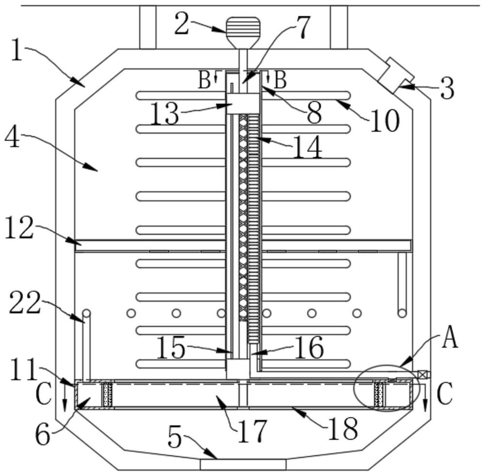
  • Heating type gravel scattering equipment for urban rail transit
  • Heating type gravel scattering equipment for urban rail transit
  • Heating type gravel scattering equipment for urban rail transit

Examples


Embodiment Construction

[0023] The following will clearly and completely describe the technical solutions in the embodiments of the present invention with reference to the accompanying drawings in the embodiments of the present invention. Obviously, the described embodiments are only some, not all, embodiments of the present invention.

[0024] In describing the present invention, it should be understood that the terms "upper", "lower", "front", "rear", "left", "right", "top", "bottom", "inner", " The orientation or positional relationship indicated by "outside", etc. is based on the orientation or positional relationship shown in the drawings, and is only for the convenience of describing the present invention and simplifying the description, rather than indicating or implying that the referred device or element must have a specific orientation, so as to Specific orientation configurations and operations, therefore, are not to be construed as limitations on the invention.

[0025] refer to Figure ...


PUM


Abstract

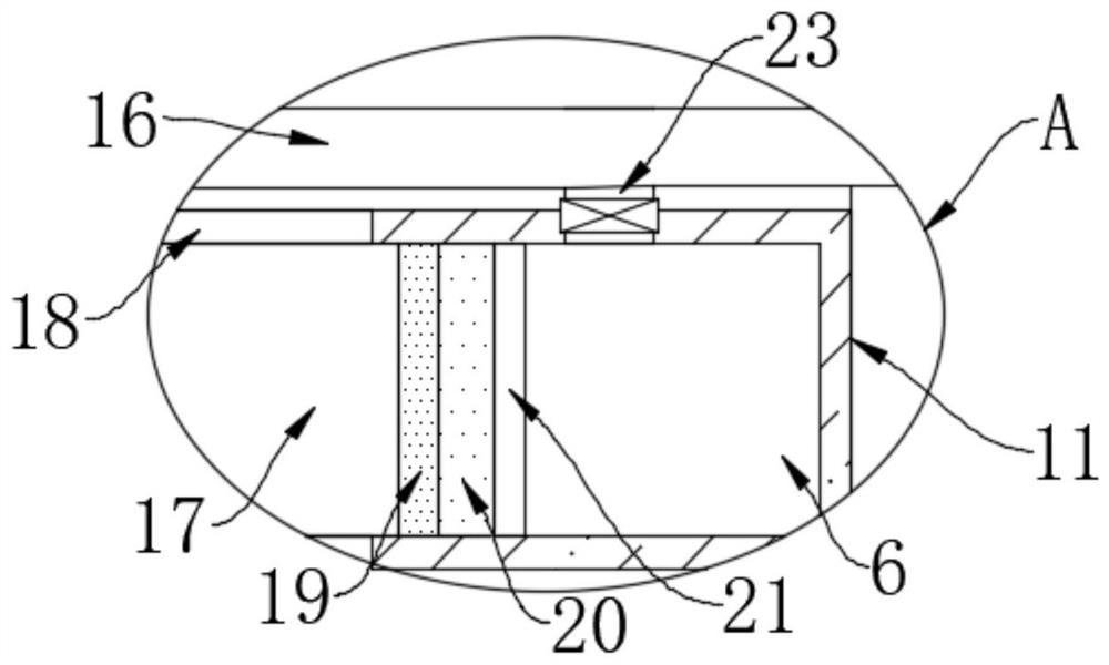
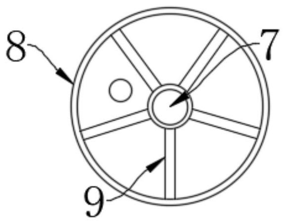
Heating type gravel scattering equipment for urban rail transit comprises a shell and a stirring mechanism. The upper end of the shell is fixedly connected with a vehicle through a plurality of vertical rods, a treatment chamber is formed in the shell, and gravel is arranged in the treatment chamber; and the stirring mechanism comprises a connecting pipe arranged in the treatment chamber, a rotating rod is arranged in the connecting pipe, the rotating rod is fixedly connected with the inner wall of the connecting pipe through a plurality of connecting rods, the upper end of the rotating rod isrotatably connected with the inner top of the treatment chamber, and a motor is mounted at the upper end of the shell. When the equipment is in use, gravel can be stirred, gravel can be discharged intermittently, use of the gravel is saved, the gravel can be heated in the stirring process, and the situation that the gravel is affected with damp, solidified and hardened, so that the sand discharging efficiency is affected is avoided.

Description

technical field [0001] The invention relates to the field of railway transportation, in particular to a heating sand spreading device for urban rail transportation. Background technique [0002] With the continuous development of society, the railway has also been greatly developed. Railway transportation has become an indispensable means of transportation in our lives. When rail vehicles need to brake during travel, sometimes it is necessary to increase the friction between the wheels and the rails. Therefore, a sand spreader is needed. The sand spreader is a device used to increase the adhesion coefficient between the wheel and rail to reduce the risk of sliding of rail vehicles. However, the sand spreader is still used during use. There will be some problems. [0003] When the traditional sand spreader is not in use, since the sand box of the sand spreader is connected to the atmosphere, the moisture will enter the sand box from the sand sprinkling port in reverse, causi...

Claims


Application Information

Patent Timeline
Patent Type & Authority Applications(China)
IPC IPC(8): B61C15/10F24H3/00
CPCB61C15/102F24H3/00
Inventor 霍伸伸
Owner 霍伸伸
Learn More