A three-point welding placement bracket positioning structure

A technology of positioning structure and positioning groove, which is applied in welding equipment, auxiliary welding equipment, welding/cutting auxiliary equipment, etc. Streamlined, accurate positioning, and accurate corresponding effects of welding points

Active Publication Date: 2021-10-22
HENGDIAN GRP DMEGC MAGNETICS CO LTD
View PDF8 Cites 0 Cited by
  • Summary
  • Abstract
  • Description
  • Claims
  • Application Information

AI Technical Summary

Problems solved by technology

[0004] In view of the problems mentioned in the background technology that the bracket is easy to run during the welding process, and the welding slag generated during the welding process affects the welding quality, etc., the present invention provides a three-point welding positioning structure for placing the bracket. Set magnets and weldment support components between them to achieve accurate positioning of the bracket before welding and effective limit during welding
[0005] Second invention purpose of the present invention is to solve the influence of welding slag on welding quality in the welding process

Method used


Image

  • A three-point welding placement bracket positioning structure
  • A three-point welding placement bracket positioning structure

Examples


Embodiment 1

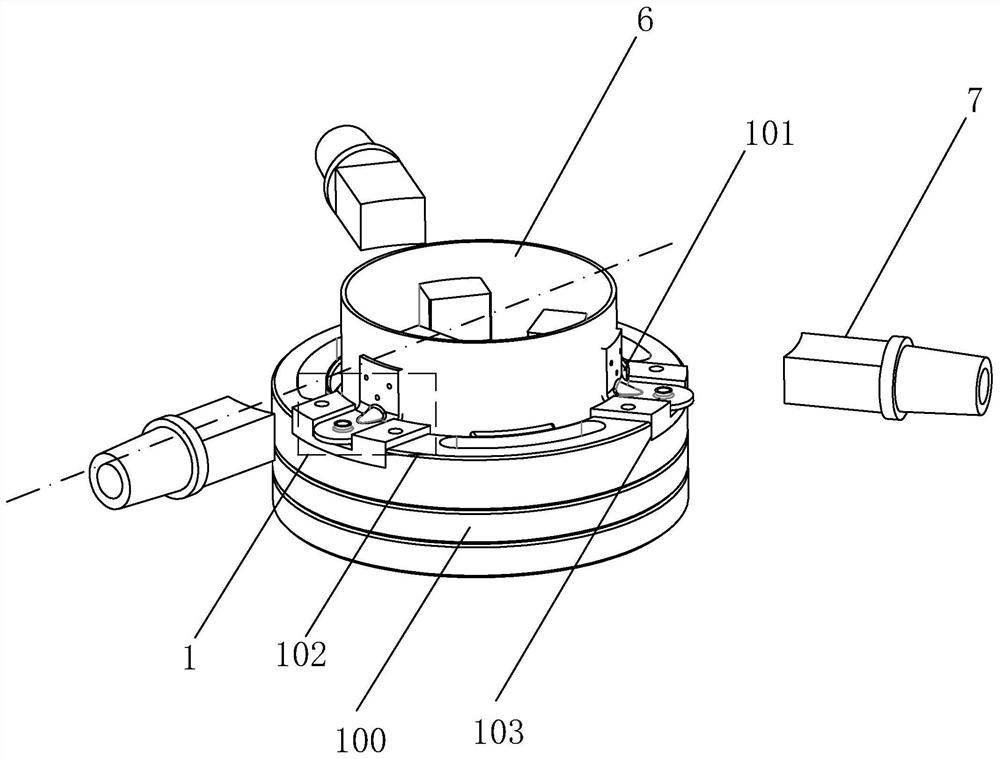
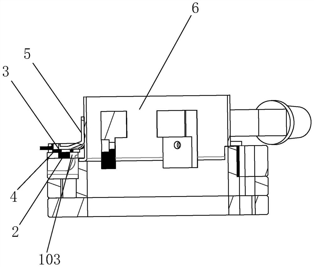
[0021] like figure 1 , 2 As shown, a three-point welding placement bracket positioning structure includes a positioning base 100 with a placement groove 101 in the middle, a base 102 is provided on the positioning base 100, and a magnet 2 is arranged in the base 102. The weldment supporting assembly 1 is arranged on the top of the base layer 102 . The magnet 2 can be fixed after the weldment support 5 is placed on the positioning abutment 100, so that no weldment running phenomenon occurs; and the weldment support separates the weldment support 5 from the positioning abutment 100, relying on The gap generated by the separation cooperates with the magnet 2 to absorb and collect the welding slag generated in the welding process of the weldment bracket 5, so as to prevent the welding slag from adhering to the vicinity of the weld bead and affect the welding quality, and effectively improve the welding accuracy and welding quality. The magnet 2 in this embodiment is a permanent ...


PUM


Abstract

The invention discloses a three-point welding bracket positioning structure, which comprises a positioning base platform provided with a placement groove in the middle, a base layer is arranged on the positioning base platform, a magnet is arranged in the base layer, and a magnet is arranged on the top of the base layer Weldment support components. The cylindrical roller converts the sliding friction between the weldment bracket and the positioning abutment into rolling friction, and effectively improves the moving ability of the weldment bracket in the positioning groove under the condition that the magnet is strongly adsorbed to the weldment bracket. After the weldment bracket is placed in the positioning groove, it can still be adjusted flexibly, so that the weldment bracket and the welding point of the motor housing in the placement groove are accurately corresponded. The two ends of the component are bent inward, thus losing the rolling ability, so that the rolling friction between the weldment support and the positioning base is converted into sliding friction again, thereby completing the stable positioning of the adjusted welding support.

Description

technical field [0001] The invention relates to the technical field of micro-motor casing bracket welding manufacturing, in particular to a three-point welding bracket positioning structure. Background technique [0002] As a basic manufacturing connection process, welding is widely used in various fields related to mechanical manufacturing. The special knuckle-shaped structure of the motor bracket is expensive to directly adopt CNC machining, and it is difficult to meet the performance requirements for casting molding, so welding molding is usually used. Due to the rapid development of welding technology and the improvement of product quality requirements, the positioning accuracy requirements for the welding joints of the motor bracket are also getting higher and higher. Especially in the installation and positioning of the EMU, the position requires high precision, and a little error of the welding joint may directly affect the stability of the motor operation, and the n...

Claims


Application Information

Patent Timeline
Patent Type & Authority Patents(China)
IPC IPC(8): B23K37/04
CPCB23K37/0426
Inventor 楼亚晖潘洋健
Owner HENGDIAN GRP DMEGC MAGNETICS CO LTD
Why Eureka
Try Eureka