


Quick Research
Generate reliable direction feasibility study reports for your R&D in just a few steps.

Technical Q&A
Discover and master advanced knowledge NOW. Basics, ideas, possibilities, all at once.

Find Solutions
As an expert in R&D theories, this can generate solutions to your technical problems instantly.

Evaluate Feasibility
Analyze your overall solution with one click, know your potential R&D risks in advance.

Monitor Landscape
Get weekly tech updates, stay abreast of the latest tech innovations and key insights.
A new energy vehicle charging pile that can automatically stop charging
A new energy vehicle, automatic stop technology, applied in the direction of electric vehicle charging technology, electric vehicles, charging stations, etc., can solve the problems such as the influence of moisture on the charging plug, short circuit, and the inability to dry well in the airtight space.
- Summary
- Abstract
- Description
- Claims
- Application Information
AI Technical Summary
Problems solved by technology
Method used
Image

Examples
Embodiment 1
[0027] as attached figure 1 to attach Figure 6 Shown:
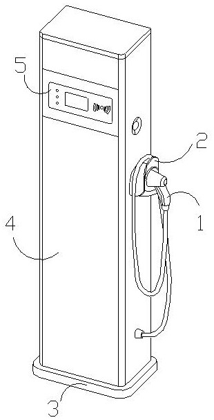
[0028] The present invention provides a new energy vehicle charging pile that can automatically stop charging. Its structure is provided with a charging plug 1, a shield 2, a bottom support 3, a body 4, and a display screen 5. The charging plug 1 is movably engaged with the shield. 2 inside, the shield 2 is embedded and installed on the right side of the body 4, the bottom support 3 is welded and connected to the lower part of the body 4, and the display screen 5 is integrated with the body 4 and is arranged in front of the body 4. side face.
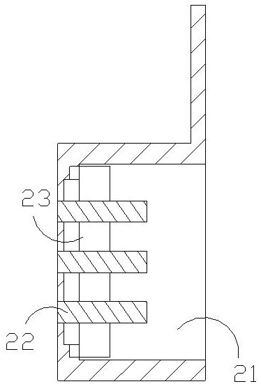
[0029] The shield 2 is provided with a front port 21, a male plug 22, and a force-bearing block 23. The front port 21 and the shield 2 are an integrated structure, and the male plug 22 is embedded and installed inside the shield 2. The force receiving body 23 moves inside the shield 2 , and the force receiving body 23 is movably engaged with the male plug 22 .
[0030] Wherein...
Embodiment 2
[0036] as attached Figure 7 Shown:
[0037] Wherein, the circular capsule body t4 is provided with a limiting ring s1, a pressure-relieving chamber s2, an adsorption block s3, and a through-cavity s4. The inside of cavity s2 is movably matched. The through cavity s4 is connected between the adsorption blocks s3. The through cavity s4 is in the shape of a ring and has holes in itself. There are four adsorption blocks s3 in a ring shape. Distributed, and made of soft rubber sponge material, the through-cavity s4 is provided with four, which are made of rubber and have a certain degree of traction, and the pressure-relieving chamber s2 is pressurized, so that the adsorption block s3 is constantly concave and bulging The activity is changed by the magnitude of the force inside the pressure-relieving chamber s2.
[0038] The specific usage and function of this embodiment: when a person inserts the charging plug 1, the extrusion force pushes the baffle a1 to move inward, and when...
PUM
 Abstract
Description
Claims
Application Information
 - R&D Engineer
- R&D Manager
- IP Professional
- Industry Leading Data Capabilities
- Powerful AI technology
- Patent DNA Extraction
Browse by: Latest US Patents, China's latest patents, Technical Efficacy Thesaurus, Application Domain, Technology Topic, Popular Technical Reports.
© 2024 PatSnap. All rights reserved.Legal|Privacy policy|Modern Slavery Act Transparency Statement|Sitemap|About US| Contact US: help@patsnap.com