Round piece cutting device for beech

A disc and beech technology, applied in the field of beech disc cutting devices, can solve the problems of safety accident sawdust or wood thorns, sticking to hands, etc., and achieve the effect of consistent cutting thickness and accurate position

Inactive Publication Date: 2020-12-15
陈幼琳
View PDF7 Cites 2 Cited by
  • Summary
  • Abstract
  • Description
  • Claims
  • Application Information

AI Technical Summary

Problems solved by technology

[0005] In order to overcome the shortcomings of manual cutting of beech, which is easy to cause safety accidents and easy to get wood chips or wood thorns on hands, the technical problem of the present invention is to provide a beech cutting machine that does not need to be fixed and moved by hand, and has high safety. Wafer device

Method used


Image

  • Round piece cutting device for beech
  • Round piece cutting device for beech
  • Round piece cutting device for beech

Examples


Embodiment 1

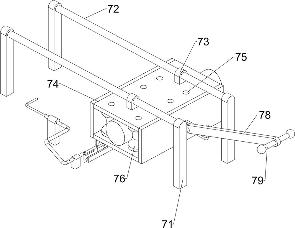
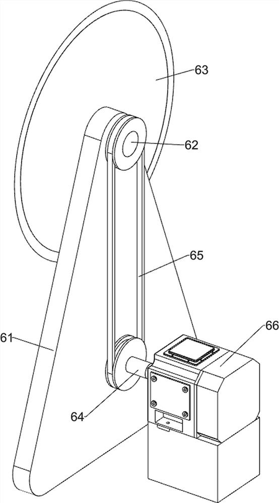
[0023] A beech wood disc cutting device, such as Figure 1-5 As shown, it includes a base 1, a support column 2, a workbench 3, a pad 4, a collection box 5, a cutting mechanism 6, and a push mechanism 7. There are five support columns 2 at the top edge of the base 1, and the top of the support column 2 There is a workbench 3 fixedly connected between them, a pad 4 is provided on the front side of the top of the workbench 3, a collection box 5 is placed on the right front side of the top of the base 1, a cutting mechanism 6 is arranged on the front side of the top of the base 1, and the cutting mechanism 6 is located on the left side of the collection box 5 Side, the top of the workbench 3 is provided with a push mechanism 7.

[0024] When people use this device, at first people put beech in the pushing mechanism 7, then start cutting mechanism 6, then just can promote pushing mechanism 7 to move to the right, treat that beech contacts with cutting mechanism 6, and cutting mech...

Embodiment 2

[0030] On the basis of Example 1, such as figure 1 with Figure 5 As shown, it also includes a fixed rod 8 and a rubber ring 9. The top of the workbench 3 is symmetrically fixedly connected with the fixed rod 8. The fixed rod 8 is provided with a rubber ring 9. The rubber ring 9 is slidably connected with the first piston 715.

[0031] When the first piston 715 moves back and forth, the rubber ring 9 can limit the movable position of the slider 712, thereby making the moving position of the push rod 713 more accurate, preventing the position deviation of the push rod 713 and not cooperating with the driving rod 77 .

[0032] Also include baffle plate 10 and guide plate 11, baffle plate 10 is provided on the rear side of the top of the pad 4, and guide plate 11 is provided on the right rear side of the top of the pad 4.

[0033] Baffle plate 10 can make the distance that beech wood moves forward consistent, and then makes the cutting thickness of disc consistent, and guide pl...


PUM


Abstract

The invention relates to a round piece cutting device, in particular to a round piece cutting device for a beech. According to the round piece cutting device for the beech, the beech does not need tobe fixed and moved manually, and the safety is high. The round piece cutting device for the beech comprises a base, a workbench, a cushion table, a collecting box, a cutting mechanism and a pushing mechanism, wherein a plurality of supporting columns are arranged at the top of the base; the workbench is arranged between the tops of the supporting columns; the cushion table is arranged on one sideof the top of the workbench; the collecting box is placed on the side, close to the cushion table, of the top of the base; the cutting mechanism is arranged on the side, close to the collecting box, of the top of the base; and the pushing mechanism is arranged on the workbench. According to the round piece cutting device, rotation of a cutter is achieved by starting a servo motor, then through cooperation of the cutting mechanism and the pushing mechanism, the pushing mechanism drives the beech to move rightwards, meanwhile, the cutting mechanism cuts the beech into round pieces, and then rapid slicing of the beech is achieved; and through cooperation of a shifting rod and an ejector rod, the beech automatically moves forwards, so that people do not need to push the beech manually.

Description

technical field [0001] The invention relates to a disc cutting device, in particular to a beech disc cutting device. Background technique [0002] In addition to the advantages of wood color, texture, and hardness, beech also has the advantages of good load-bearing performance and good compression resistance. It is often used in the production of furniture, wooden doors, floors, handicrafts or toys. [0003] People usually cut beech wood into round pieces, and then use the round pieces to make toys. When people cut beech wood, they usually place the beech wood on the workbench, and then manually move the beech wood to make the cutting knife cut the beech wood into round pieces. And this just makes staff and cutting knife distance closer, thus easily produces safety accident, and also easily stains wood dust or wood thorn on the hand like this, and then makes people's hand produce discomfort. [0004] Therefore need to design a kind of device that does not need to fix and mo...

Claims


Application Information

Patent Timeline
Patent Type & Authority Applications(China)
IPC IPC(8): B27C5/02B27C5/06
CPCB27C5/02B27C5/06
Inventor 陈幼琳
Owner 陈幼琳
Why Eureka
Try Eureka