
Automatic assembly device for piston rod sealing element

An automatic assembly and sealing technology, which is applied in metal processing equipment, assembly machines, metal processing, etc., can solve the problems of high labor intensity for operators, unguaranteed product quality, and easy scratching of sealing rings, etc. Stable and reliable, small deformation, high assembly efficiency

Active Publication Date: 2020-12-15
SHANDONG ATAW IND ROBOT TECH
View PDF9 Cites 4 Cited by
  • Summary
  • Abstract
  • Description
  • Claims
  • Application Information

AI Technical Summary

Problems solved by technology

The inner size of the sealing ring is several millimeters smaller than the outer diameter of the piston rod. Manual assembly is laborious, the assembly efficiency is low, the process is uncontrollable, and the quality cannot be guaranteed. Therefore, the assembly of piston rod seals has become a constraint for the rapid development of the oil cylinder industry. Conditions, the current assembly of the piston rod seal is mainly to manually put the sealing ring on the piston rod to be installed. Since the sealing ring is difficult to expand, manual operation is very laborious. Usually, a screwdriver or manual assembly tool is used to open the sealing ring and pry it into the waiting Installed in the sealing groove on the piston rod, the guide sleeve and the stopper are manually stretched and placed in the sealing groove of the piston rod, but the sealing ring of the existing production equipment is easily scratched, resulting in internal leakage and sealing failure, and the product quality cannot be guaranteed. The labor intensity of the operator is high, and it is dangerous at the same time. For this purpose, an automatic assembly equipment for piston rod seals is designed.

Method used


Image

  • Automatic assembly device for piston rod sealing element
  • Automatic assembly device for piston rod sealing element
  • Automatic assembly device for piston rod sealing element

Examples


Embodiment Construction

[0033] The present invention will be described in further detail below in conjunction with the accompanying drawings and specific implementation.

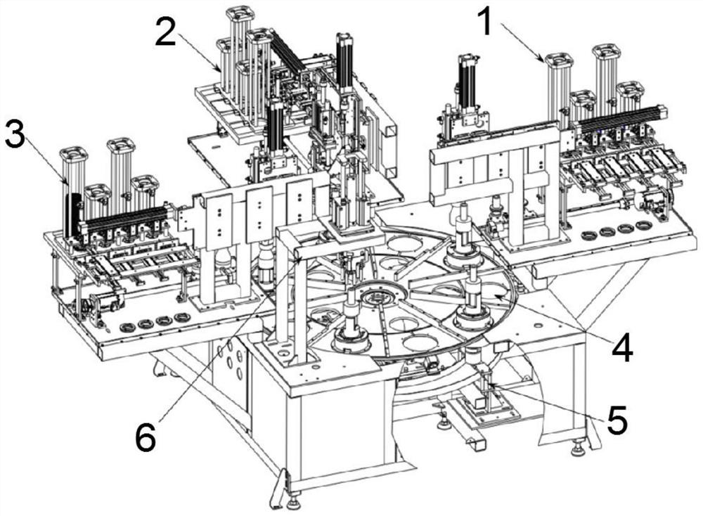
[0034] An automatic assembly equipment for piston rod seals, comprising seal assembly unit one 1, seal assembly unit two 2, seal assembly unit three 3, servo rotation unit 4, pneumatic jacking unit 5, and shaping unit 6, the servo The rotating unit 4 is arranged on the top side of the pneumatic jacking unit 5, the shaping unit 6 is arranged on the left side of the top front of the servo rotating unit 4, and the seal assembly unit 1 is arranged on the top of the servo rotating unit 4. On the left side of the surface, the second seal assembly unit 2 is arranged on the rear side of the top surface of the servo rotation unit 4 , and the third seal assembly unit 3 is arranged on the right side of the top surface of the servo rotation unit 4 .

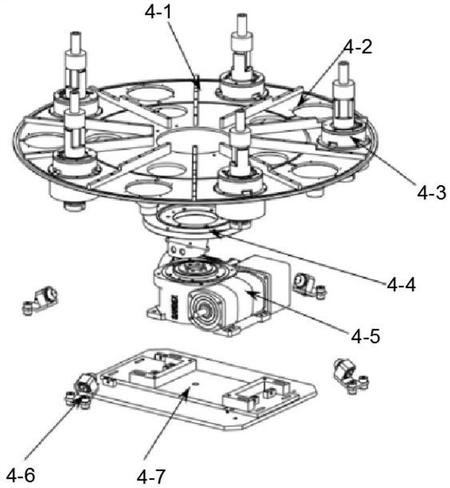
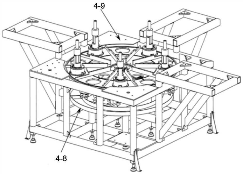
[0035] The servo rotation unit 4 is composed of a reinforcing rib 4-1, a rotary table 4-2, a ...


PUM


Abstract

The invention relates to an automatic assembly device for a piston rod sealing element, comprising a first sealing element assembly unit, a second sealing element assembly unit, a third sealing element assembly unit, a servo rotating unit, a pneumatic jacking unit and a shaping unit. The servo rotating unit is arranged on the top side of the pneumatic jacking unit; the shaping unit is arranged onthe front left side of the top surface of the servo rotating unit; and the first sealing element assembly unit, the second sealing element assembly unit and the third sealing element assembly unit arearranged on the top surface of the servo rotating unit. The whole layout is high in automation degree; labor is completely released; the assembly efficiency is high; the assembly process is stable, reliable and safe; the layout is reasonable; a taper sleeve is adopted for sealing member assembly; the sealing member deformation is small; the stress concentration is avoided; the sealing member damage is small; the blocking sheet assembly is achieved; quick loading of sealing members can be achieved; the sleeve is elastically pressed; and the structure design is reasonable. In the process that asealing ring is pressed and pushed downwards along the taper sleeve, the sealing ring cannot distort and deform and is suitable for application and popularization.

Description

technical field [0001] The invention relates to the field of computer-aided equipment, in particular to an automatic assembly equipment for piston rod seals. Background technique [0002] The piston rod is one of the key parts of the hydraulic mechanical cylinder. The piston rod is equipped with multiple seals, seal rings, support rings and baffles. The support ring and the retainer have oblique openings, which are convenient for manual assembly. The inner size of the sealing ring is several millimeters smaller than the outer diameter of the piston rod. Manual assembly is laborious, the assembly efficiency is low, the process is uncontrollable, and the quality cannot be guaranteed. Therefore, the assembly of piston rod seals has become a constraint for the rapid development of the oil cylinder industry. Conditions, the current assembly of the piston rod seal is mainly to manually put the sealing ring on the piston rod to be installed. Since the sealing ring is difficult to ...

Claims


Application Information

Patent Timeline
IPC IPC(8): B23P19/00B23P21/00
CPCB23P19/00B23P21/00
Inventor 耿金碧景年强张衡陈哲
Owner SHANDONG ATAW IND ROBOT TECH
Learn More