
Metal gasket blanking die for machining

A metal gasket and mechanical processing technology, applied in the direction of pushing out equipment, etc., can solve the problems of accumulation inside the blanking hole, unsmooth discharge, easy scratching of the wall of the blanking hole, etc., so as to avoid accumulation and facilitate discharge Effect

Inactive Publication Date: 2020-12-15
李存贺
View PDF0 Cites 4 Cited by
  • Summary
  • Abstract
  • Description
  • Claims
  • Application Information

AI Technical Summary

Problems solved by technology

[0003] When processing metal sealing gaskets, most of them are formed by punching a whole metal base plate through a punching die. In the prior art, when punching a metal base plate, the cutting edge and blanking hole of the punching tool are used The upper cutting edges cooperate with each other to form partial shear on the metal base plate to form a metal gasket. The punched metal gasket is automatically discharged from the blanking hole, but the metal gasket is easy to scratch and blank during the discharge process. The wall of the hole makes the metal gaskets accumulate inside the blanking hole, making it impossible to discharge smoothly

Method used


Image

  • Metal gasket blanking die for machining
  • Metal gasket blanking die for machining
  • Metal gasket blanking die for machining

Examples


Embodiment 1

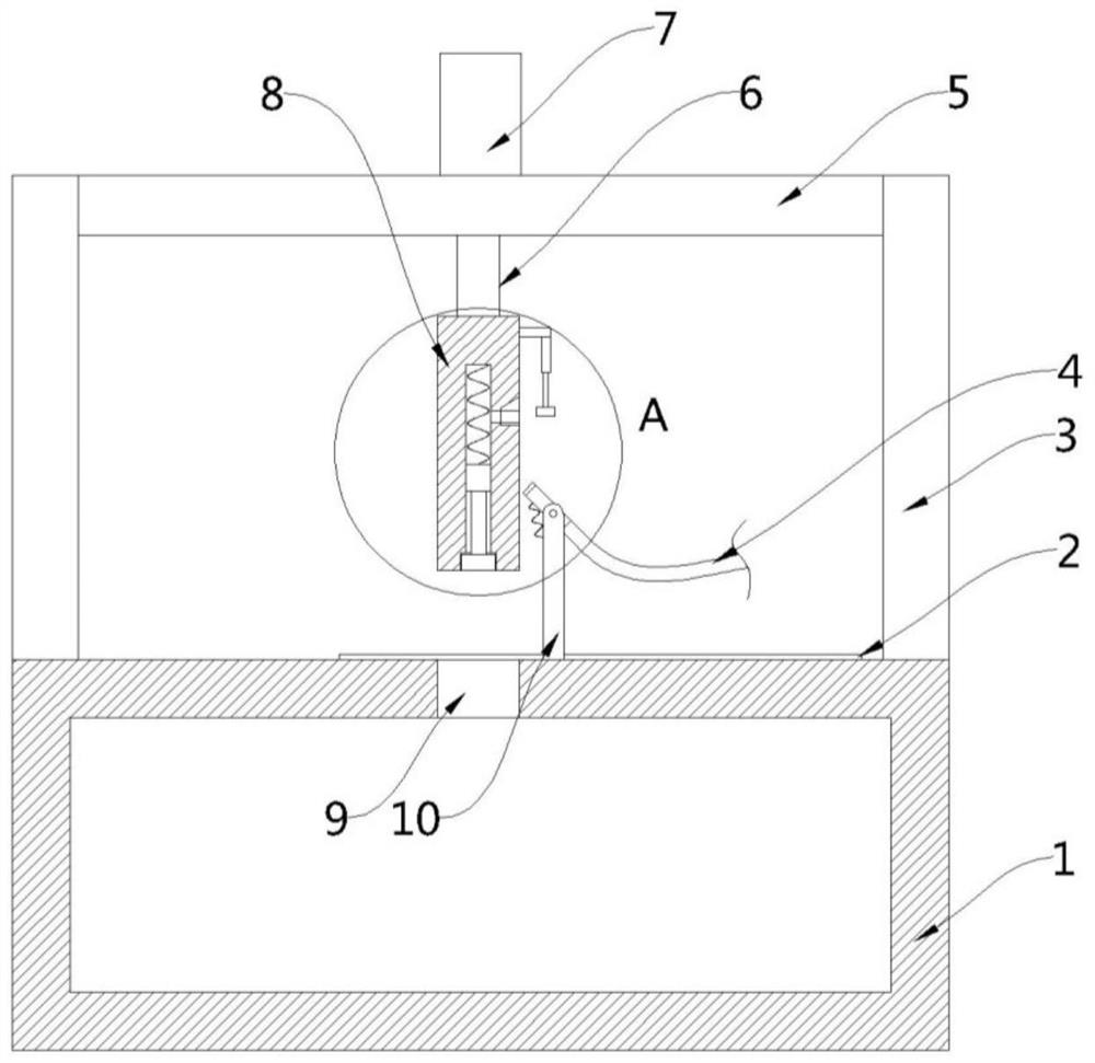
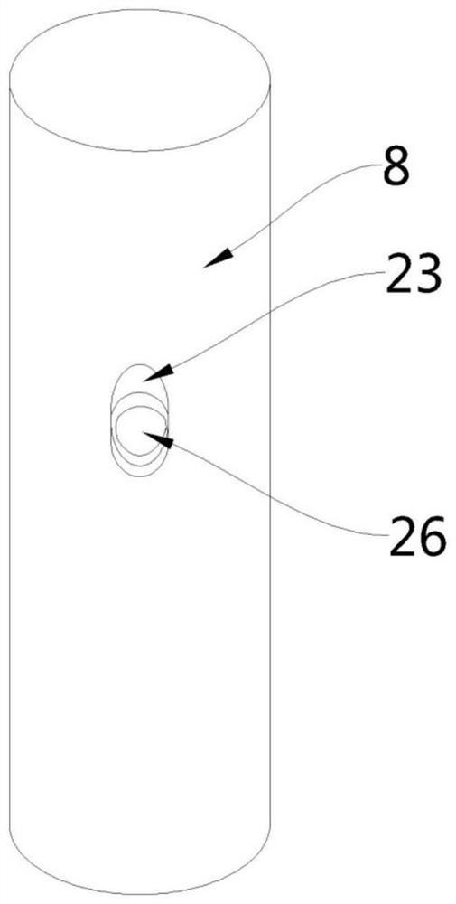
[0024] see Figure 1-3 , this embodiment provides a metal gasket blanking die for mechanical processing, including a bottom box 1, a blanking hole 9 is opened in the upper middle of the bottom box 1, and two groups of mutually symmetrical holes are fixed on the upper edge of the bottom box 1 Support vertical plate 3, two groups of support vertical plate 3 tops are connected by support horizontal plate 5, between two groups of support vertical plate 3, be provided with punching tool 8 corresponding to described blanking hole 9, described support horizontal plate 5 A power assembly for driving the punching tool 8 to move downward is installed on the top, a limiting groove 15 is provided at the bottom of the punching tool 8, and an installation channel 11 communicating with the limiting groove 15 is arranged inside the punching tool 8 , the inside of the limiting groove 15 is movably embedded with a pusher head 16, the inside of the installation channel 11 is movably provided wit...

Embodiment 2

[0033] see figure 2, a metal gasket blanking die for mechanical processing. Compared with Embodiment 1, the end of the intake hard pipe 17 away from the intake hose 4 is also provided with a sealing ring 20 in this embodiment. 17 is transferred from the wedge-shaped notch 23 to the inside of the air intake hole 26, and the sealing ring 20 abuts against the inner wall of the air intake hole 26, thereby improving the sealing effect and ensuring that the compressed air can smoothly drive the piston 13, The connecting rod 14 and the pushing head 16 move down.

[0034] Specifically, the sealing ring 20 is made of rubber material.

[0035] In the embodiment of the present invention, after the blanking tool 8 punches the metal substrate 2, the pressure tube assembly can drive the intake hard tube 17 to rotate, so that one end of the intake hard tube 17 is docked with the air intake hole 26, and the external supply is used to The pneumatic equipment injects compressed air into the ...


PUM


Abstract

The invention provides a metal gasket blanking die for machining, and belongs to the technical field of metal gasket machining. The metal gasket blanking die comprises a bottom box, a discharging holeis formed in the middle of the upper part of the bottom box, two groups of mutually symmetrical support vertical plates are fixedly arranged at the edge of the upper part of the bottom box, and the upper parts of the two groups of support vertical plates are connected through a support transverse plate; and a blanking tool corresponding to the discharging hole is arranged between the two groups of support vertical plates. In the embodiment of the invention, after a metal base material is blanked by the blanking tool, a pipe pressing assembly can drive an air inlet hard pipe to rotate, so thatone end of the air inlet hard pipe is in butt joint with an air inlet hole, and compressed air is injected into a mounting channel through an air inlet hose and the air inlet hard pipe by utilizing external air supply equipment so as to drive a piston, a connecting rod and a material pushing head to move downwards; and the blanked metal sheets are pushed into the bottom box from the discharging hole, automatic discharging of the metal sheets is achieved, the metal sheets are prevented from being accumulated in the discharging hole, and the advantage of being convenient to discharge is achieved.

Description

technical field [0001] The invention belongs to the technical field of metal gasket processing, in particular to a metal gasket blanking die for mechanical processing. Background technique [0002] Sealing gasket is a kind of sealing spare parts used in machinery, equipment and pipelines as long as there is fluid. It uses internal and external materials to play a sealing role. Sealing gaskets are made of metal or non-metallic plate materials through cutting, stamping or cutting processes, and are used for the sealing connection between pipes and the sealing connection between parts of machinery and equipment. [0003] When processing metal sealing gaskets, most of them are formed by punching a whole metal base plate through a punching die. In the prior art, when punching a metal base plate, the cutting edge and blanking hole of the punching tool are used The upper cutting edges cooperate with each other to form partial shear on the metal base plate to form a metal gasket. T...

Claims


Application Information

Patent Timeline
Patent Type & Authority Applications(China)
IPC IPC(8): B21D28/02B21D28/14B21D45/02
CPCB21D28/02B21D28/14B21D45/02
Inventor 李存贺
Owner 李存贺
Learn More