
Protection device of computer power interface

A computer power supply and protection device technology, applied in the computer field, can solve problems such as poor contact, power cord falling off, and accelerated computer aging

Active Publication Date: 2020-12-11
GUANGDONG PEIZHENG COLLEGE
View PDF8 Cites 5 Cited by
  • Summary
  • Abstract
  • Description
  • Claims
  • Application Information

AI Technical Summary

Problems solved by technology

[0003] When the computer is in use, it must be connected to the current to provide it with a source of working power. Therefore, it is usually necessary to use a wire to connect the computer to an external power supply. In order to facilitate the replacement of the power cord, a power interface is usually provided on the back of the computer. , one end of the special wire is connected to the power interface of the computer, and the other end is connected to the external power supply. It is easy to make the power cord fall off from the power interface due to accidental touch or pulling on the wire, and when the computer is idle, the power interface is in an open state. At this time, dust can easily enter the interface and speed up the computer. The aging of the computer makes it prone to poor contact during later use, so it is necessary to provide a protective device for the computer power interface to solve the above problems

Method used


Image

  • Protection device of computer power interface
  • Protection device of computer power interface
  • Protection device of computer power interface

Examples


Embodiment 1

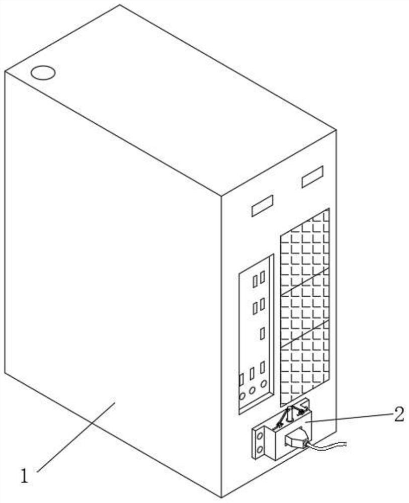
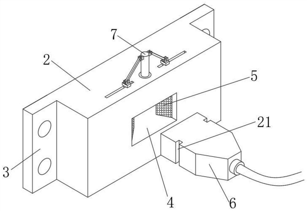
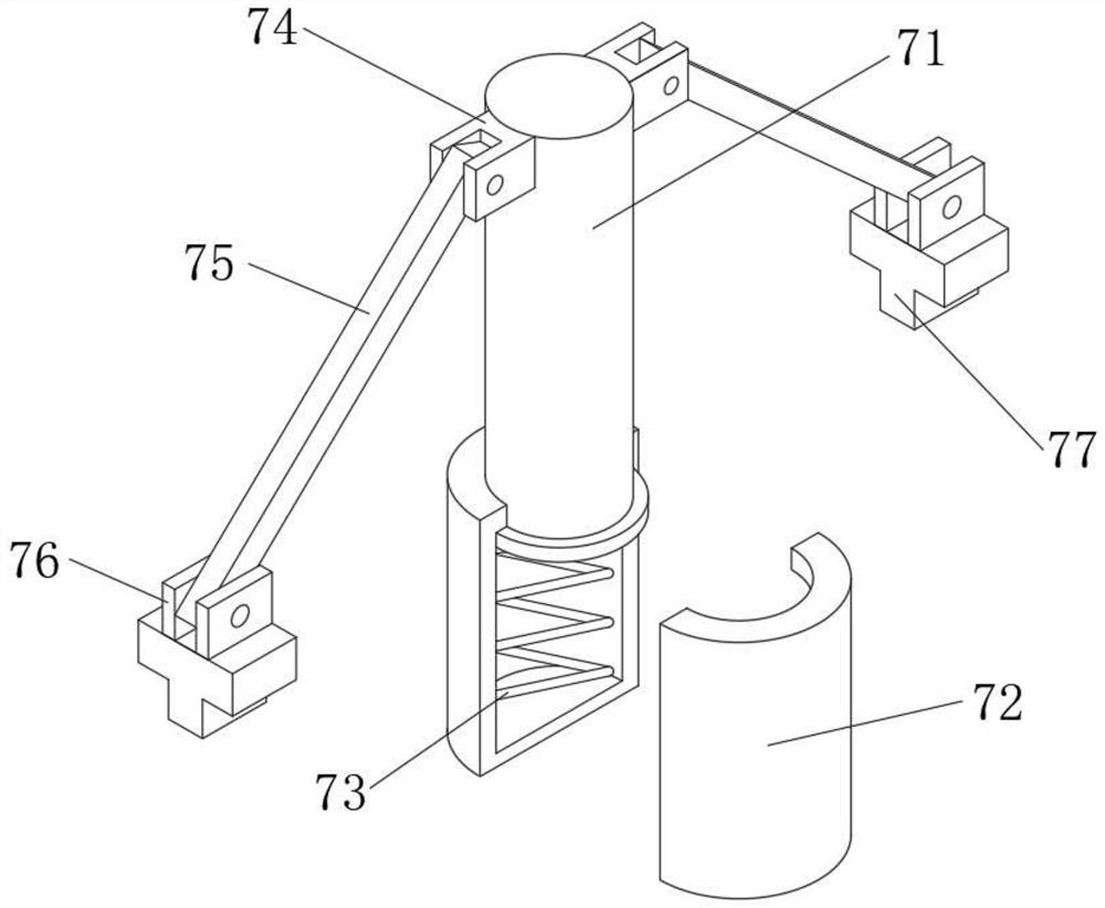
[0036] Such as Figure 1-7 The protection device for a computer power interface shown includes a chassis 1, the back of the chassis 1 is fixedly connected with a fixing seat 2, and the outer surface of the fixing seat 2 is provided with a slot 4, and both sides of the inner wall of the slot 4 are movably engaged. There is a triangular block 5, and the inside of the slot 4 is movably plugged with a power cord plug 6, and both sides of the power cord plug 6 are provided with limited slots 21, and both sides of the power cord plug 6 are movably clamped with the triangular block 5, and the fixed seat The upper surface of 2 is fixedly connected with an adjustment assembly 7, and the two sides of the adjustment assembly 7 are slidably connected to the upper surface of the fixed seat 2 and fixedly connected with the triangular block 5. The side of the triangular block 5 is fixedly connected with the first rack 8, and the fixed seat The inside of 2 is rotatably connected with a gear 1...

Embodiment 2

[0038] Such as Figure 1-7 The protection device for a computer power interface shown includes a chassis 1, the back of the chassis 1 is fixedly connected with a fixing seat 2, and the outer surface of the fixing seat 2 is provided with a slot 4, and both sides of the inner wall of the slot 4 are movably engaged. There is a triangular block 5, and the inside of the slot 4 is movably plugged with a power cord plug 6, and both sides of the power cord plug 6 are provided with limited slots 21, and both sides of the power cord plug 6 are movably clamped with the triangular block 5, and the fixed seat The upper surface of 2 is fixedly connected with an adjustment assembly 7, and the two sides of the adjustment assembly 7 are slidably connected to the upper surface of the fixed seat 2 and fixedly connected with the triangular block 5. The side of the triangular block 5 is fixedly connected with the first rack 8, and the fixed seat The inside of 2 is rotatably connected with a gear 1...

Embodiment 3

[0040] Such as Figure 1-7The protection device for a computer power interface shown includes a chassis 1, the back of the chassis 1 is fixedly connected with a fixing seat 2, and the outer surface of the fixing seat 2 is provided with a slot 4, and both sides of the inner wall of the slot 4 are movably engaged. There is a triangular block 5, and the inside of the slot 4 is movably plugged with a power cord plug 6, and both sides of the power cord plug 6 are provided with limited slots 21, and both sides of the power cord plug 6 are movably clamped with the triangular block 5, and the fixed seat The upper surface of 2 is fixedly connected with an adjustment assembly 7, and the two sides of the adjustment assembly 7 are slidably connected to the upper surface of the fixed seat 2 and fixedly connected with the triangular block 5. The side of the triangular block 5 is fixedly connected with the first rack 8, and the fixed seat The inside of 2 is rotatably connected with a gear 10...


PUM


Abstract

The invention discloses a protection device for a computer power interface, and relates to the field of computers. According to the protection device for the computer power interface, a fixing base isfixedly connected to the back face of a case, an inserting groove is formed in the outer surface of the fixing base, triangular blocks are movably clamped to the two sides of the inner wall of the inserting groove, a power line plug is movably inserted into the inserting groove, and limiting grooves are formed in the two sides of the power line plug; the two sides of the power line plug are movably clamped with the triangular block, the upper surface of the fixing base is fixedly connected with an adjusting assembly, the two sides of the adjusting assembly are slidably connected to the uppersurface of the fixing base and fixedly connected with the triangular block, the side face of the triangular block is fixedly connected with a first rack, a gear is rotatably connected into the fixingbase, and the first rack is engaged with the gear. According to the protection device for the computer power interface, the power line plug is clamped and fixed in use, so that the power line plug isprevented from falling off from the power interface, and meanwhile, a dustproof effect on the power interface is achieved when the protection device is not used.

Description

technical field [0001] The invention relates to the technical field of computers, in particular to a protection device for a computer power interface. Background technique [0002] Computer, commonly known as computer, is a modern electronic computing machine used for high-speed computing. It can perform numerical calculations, logic calculations, and storage and memory functions. It is a modern intelligent electronic device that can run according to programs and process massive amounts of data automatically and at high speed. The equipment is composed of hardware system and software system, which can be divided into supercomputer, industrial control computer, network computer, personal computer, and has an extremely important impact on human production activities and social activities. The application has expanded to all fields of society, and a huge computer industry has been formed, which has driven technological progress on a global scale, which has triggered profound so...

Claims


Application Information

Patent Timeline
Patent Type & Authority Applications(China)
IPC IPC(8): H01R13/639H01R13/502H01R13/52H01R13/633G06F1/26G06F21/85
CPCH01R13/639H01R13/5213H01R13/633H01R13/502G06F1/26G06F21/85H01R2201/06
Inventor 龚健虎
Owner GUANGDONG PEIZHENG COLLEGE
Learn More